Fluid transfer assembly for pharmaceutical delivery system and method for using same

a technology of fluid transfer and pharmaceutical delivery system, which is applied in the field of fluid transfer assembly for pharmaceutical delivery system, can solve the problems of accidental pricking, affecting the sterility of the needle, and particularly dangerous accidents, and achieves the effect of reducing the possibility of accidental pricking and sufficient length

Inactive Publication Date: 2010-03-16
DUOJECT MEDICAL SYSTEMS INC
View PDF36 Cites 66 Cited by
  • Summary
  • Abstract
  • Description
  • Claims
  • Application Information

AI Technical Summary

Benefits of technology

[0030]e) advancing the vial socket assembly relative to the housing, causing the conduit to advance from the retracted position to the activated position to fluidly connect the chamber of the vessel and the inner chamber of the vial; and
[0046]Advantageously, embodiments of the invention employing a vial with an inner wall tapering toward a point or apex, such as vials of a class called maximum recovery vials, allow for a small amount of fluid to be stored in, or mixed within, the vial and to be withdrawn so as to leave behind only a small fraction of the fluid volume. Particularly advantageously, providing the small diameter second compartment below the larger first compartment allows a drug-containing fluid of about 0.5 mL to be contained within the inner chamber and then lyophilized to form a powder. The powder collects in the second compartment and is mixed with a viscous diluent of about 0.1 mL injected from the vessel. The viscosity of the diluent may be between about 1 and 100 cP, but is preferably between about 60 and 80 cP.
[0047]The relative viscosity and small diameter of the second compartment (for example in the order of about 3 mL) serve to induce a sufficient surface tension of the fluid mixture within the second compartment so that the fluid mixture does not leave the second compartment, even if the vial is inverted. This advantageously avoids the possibly of the fluid mixture coating the walls of the first compartment or penetrable seal, which would reduce the recovery rate of the fluid mixture and lead to wastage of the drug.
[0049]Further, a pharmaceutical transfer assembly employing the modified vial socket assembly advantageously provides a piercing conduit, such as a hollow needle, longer than that conventionally used to pierce the top seal of a vial. This long needle has a length dimension sized to extend the length of the inner chamber of the vial, so that the tip of the needle (and the aperture in the tip) is positioned closely adjacent the apex of the inner chamber. This narrowing of the inner chamber to an apex and placement of the needle aperture adjacent thereto assists to ensure that as much of the fluid as possible can be withdrawn from the vial. This is because the tapering of the inner chamber towards a downward apex causes the fluid in the inner chamber to tend to collect at the apex.
[0050]Further advantageously, the vial socket assembly may have a cylindrical wall for receiving a substantial part of the vial within the cylindrical wall. The cylindrical wall of the vial socket assembly preferably extends longitudinally beyond the tip of the hollow needle. Thus, the cylindrical wall serves to reduce the possibility of accidental pricking or other damaging contact with the needle when the vial is not received in the vial socket assembly. Further, the cylindrical wall has sufficient length to substantially overlie most, if not all, of the outer wall of the vial, when the vial is received in the vial socket assembly. The vial socket assembly may also have a flange extending outward from the cylindrical wall near its open end, in order to assist with manual insertion of the vial into the vial socket assembly.

Problems solved by technology

Firstly, the user is exposed to the unprotected needle tip, which can result in accidental stabbings or prickings to the user.
Secondly, if the user wishes to draw a large volume of the pharmaceutical component into the syringe (e.g., 10 cc) an equivalent volume of air must be forced into the vial.
These accidents are particularly dangerous if the pharmaceutical component is unsafe to the user, for example where it includes toxic oncology pharmaceuticals.
Thirdly, the sterility of the needle may be compromised during the process of transferring the pharmaceutical component from the vial to the syringe.
These methods suffer from many of the disadvantages described above.
In some cases, the composition can be relatively viscous, which may tend to cause some of the composition to remain or be “held up” in the vial.
These types of pharmaceutical compositions tend to be very expensive both to manufacture and administer.
Such caking of the lyophilized pharmaceutical component on the vial walls can make mixing of the component with a diluent more difficult.

Method used


Image

  • Fluid transfer assembly for pharmaceutical delivery system and method for using same
  • Fluid transfer assembly for pharmaceutical delivery system and method for using same
  • Fluid transfer assembly for pharmaceutical delivery system and method for using same

Examples


Embodiment Construction

[0080]The pharmaceutical transfer assemblies described herein may be used with a standard pharmaceutical vial and a standard syringe or slightly modified versions thereof. However, some other embodiments of the transfer assembles may use a special form of vial, which falls within a class of vials called maximum recovery vials. Such other embodiments are shown and described in relation to FIGS. 54 to 58.

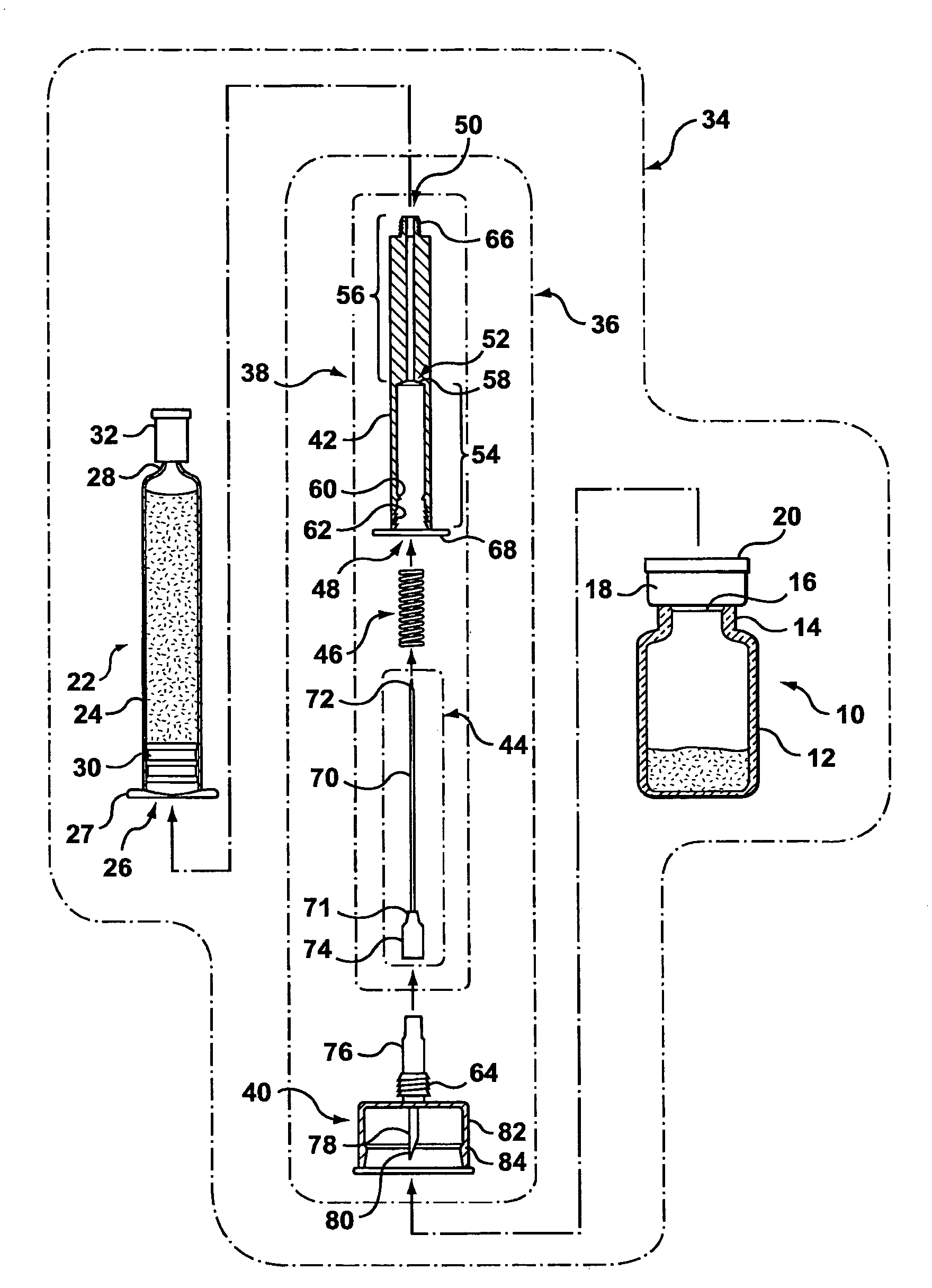
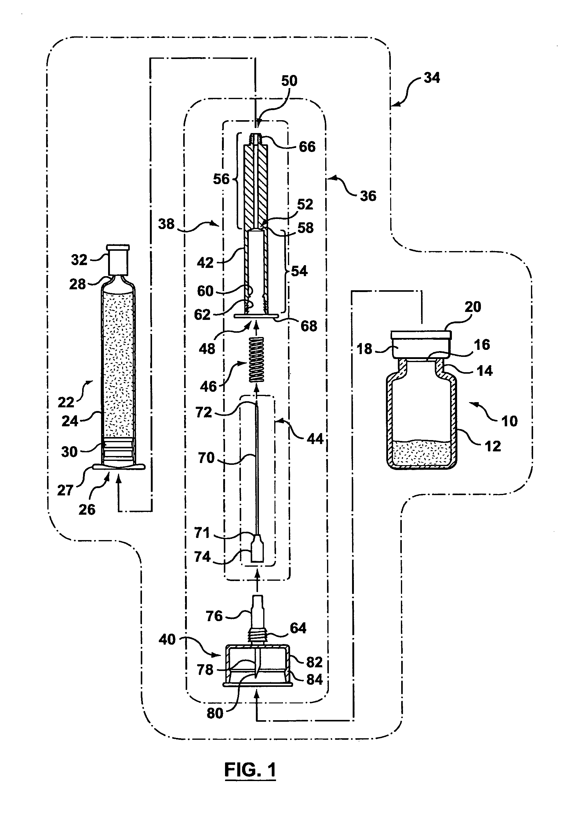
[0081]As best seen in FIG. 1, a standard pharmaceutical vial 10 generally has a vial body 12, a neck 14 of a reduced diameter compared with the body 12, a penetrable closure 16 made of an elastomeric material (e.g. rubber), a cap 18 to hold the penetrable closure 16 onto the pharmaceutical vial 10, and a cover 20 to protect the integrity of the penetrable closure 16 before use.

[0082]Still referring to FIG. 1, a standard syringe 22 may be a glass syringe having a syringe body 24 being open at one end 26 and having a neck 28 at the opposite end. A piston 30 is lodged in the syringe body...


PUM


Abstract

The present invention provides a transfer assembly for transferring a fluid between a vessel and a vial and a method for using same. The vial may be a maximum recovery vial. The vessel has a body with an open end and a slidable piston positioned within the body through the open end. The maximum recovery vial has an inner chamber with an open end and a closed end and a penetrable seal covering the open end of the inner chamber. The transfer assembly includes a housing having first and second open ends and a bore extending between the first and second open ends. The housing is connectable to the piston. The transfer assembly also includes a conduit having first and second ends and first and second apertures adjacent to the first and second ends, respectively. The conduit is longitudinally slidable within the bore between a retracted position in which the first aperture is positioned within at least one of the housing and the piston when the housing is connected to the piston, and an activated position in which the first aperture protrudes through the piston into the body of the vessel when the housing is connected to the piston. The transfer assembly also includes a vial socket assembly having a vial socket and a hollow piercing member. The vial socket is sized and shaped for receiving and engaging at least a portion of the maximum recovery vial including the penetrable seal. The hollow piercing member has a first open end in fluid communication with the conduit and a second open end for piercing the penetrable seal of the maximum recovery vial. The hollow piercing member is sized to extend substantially the full length of the inner chamber of the maximum recovery vial when the maximum recovery vial is fully engaged in the vial socket. The vial socket assembly is moveable longitudinally relative to the housing in concert with the conduit.

Description

CROSS REFERENCE TO RELATED APPLICATIONS[0001]This application is a continuation-in-part of co-pending U.S. patent application Ser. No. 10 / 540,230, entitled “Pharmaceutical delivery systems and methods for using same”, which is the National Stage of International Application No. PCT / CA2004 / 000064, filed Jan. 22, 2004, which claims the benefit of U.S. Provisional Application No. 60 / 441,352 filed on Jan. 22, 2003 and U.S. Provisional Application No. 60 / 518,345 filed on Nov. 10, 2003.FIELD OF THE INVENTION[0002]The present invention generally relates to fluid transfer assemblies for pharmaceutical delivery systems, and to methods for using same. More specifically, it relates to an assembly for transferring one or more components of a pharmaceutical composition from a pharmaceutical vial to a syringe or vice versa.BACKGROUND OF THE INVENTION[0003]Traditionally, a syringe is filled manually by aspirating a liquid pharmaceutical component from a pharmaceutical vial having a neck with a pen...

Claims


Application Information

Patent Timeline
Patent Type & Authority Patents(United States)
IPC IPC(8): B01L3/02B01L99/00
CPCA61J1/2096A61J2001/2013A61J2001/2051A61J2001/2055A61J1/201A61J1/2013A61J1/2051A61J1/2055
Inventor REYNOLDS, DAVID L.MACDONALD, DANIELTREPANIER, JULIE
Owner DUOJECT MEDICAL SYSTEMS INC
Why Eureka
Try Eureka