Solid electrolytic capacitor

a technology of electrolytic capacitors and solids, applied in the direction of electrolytic capacitors, capacitor details, capacitor dielectric layers, etc., to achieve excellent heat radiation properties, excellent strength, and shorter conductive paths

Active Publication Date: 2017-10-05
JAPAN CAPACITOR IND
View PDF13 Cites 9 Cited by
  • Summary
  • Abstract
  • Description
  • Claims
  • Application Information

AI Technical Summary

Benefits of technology

[0035]The cathode terminal is preferably a metal plate. The metal plate has an excellent heat radiation property as compared to a printed substrate and a resin plate. Unlike the printed substrate, the metal plate does not require formation of a through-hole conductor or a via conductor for wiring the capacitor element and a mounting-side terminal, but provides conductive paths on the entire surface thereof, thereby achieving shorter conductive paths.
[0036]In addition, the metal plate has excellent strength even with a small thickness, which is advantageous for reduction in the height of the solid electrolytic capacitor. Moreover, the metal plate is inexpensive as compared to the printed substrate, which is advantageous for reduction in cost of the solid electrolytic capacitor.
[0037]According to the present invention, because the lengths of conductive paths near the anode terminals can be shortened, parasitic inductances generated on the conductive paths near the anode terminals can be reduced, thereby improving noise removal performance of a solid electrolytic capacitor in a high frequency band.
[0038]As described above, according to the present invention, since both end faces of the core portion of the through conductor are in contact with the pair of anode terminals, respectively, this contact can be planar contact on relatively large areas. This configuration can maintain, at a low value, resistance at electrically connected parts between the core portion of the through conductor and the anode terminals. Accordingly, large current is allowed to flow through the solid electrolytic capacitor.
[0039]According to the present invention, the anode terminals, which do not contribute to capacitance formation, are disposed on the end faces of the core portion of the through conductor are directly in contact with the anode terminals, and thus a member which does not contribute to capacitance formation occupies a relatively small fraction of the entire volume, leading to high a volumetric efficiency. This configuration is thus suitable for achieving size reduction and large capacitance. The noise removal performance can be increased in a frequency band attributable to capacitance. Thus, according to the present invention, the noise removal performance can be increased in a wide frequency band including a high frequency band attributable to parasitic inductance and a frequency band attributable to capacitance.
[0040]According to the present invention, the functionalities of the two components of the porous sintered body 2 and the anode wire 3 in the solid electrolytic capacitor 1 disclosed in WO 2005 / 015588 A and illustrated in FIG. 8 can be achieved by the single component of the through conductor including the core portion and the porous portion, thereby achieving reduction in the number of components and thus in cost.

Problems solved by technology

However, the above-described solid electrolytic capacitor 1 has a problem to be solved as described below.

Method used


Image

  • Solid electrolytic capacitor
  • Solid electrolytic capacitor
  • Solid electrolytic capacitor

Examples


first embodiment

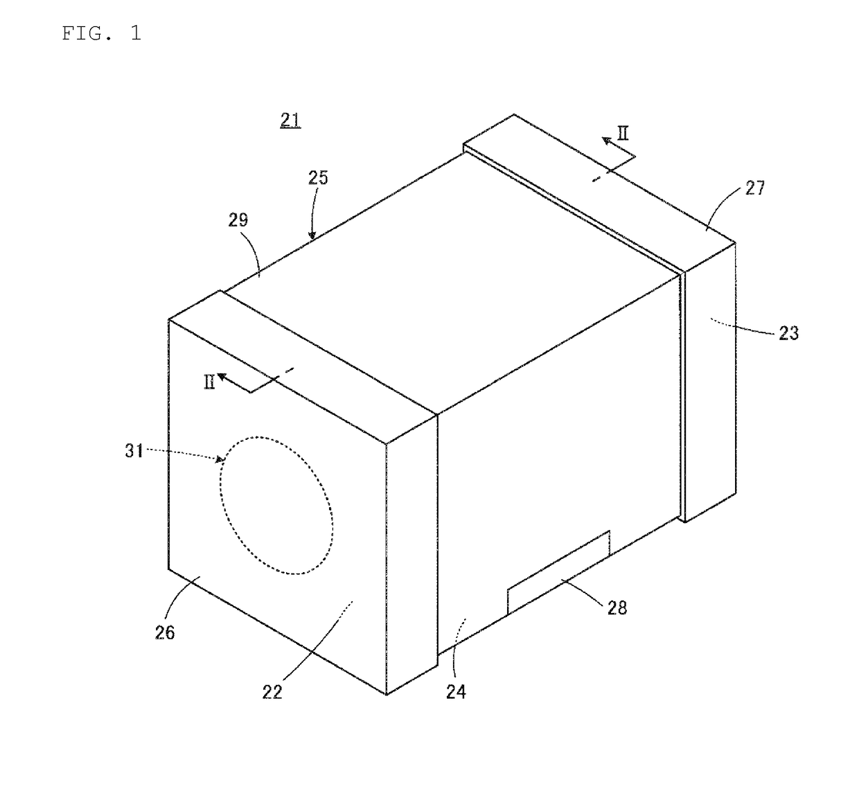
[0050]The following describes a solid electrolytic capacitor 21 according to the present invention with reference to FIGS. 1 to 5.

[0051]The solid electrolytic capacitor 21 includes a rectangular parallelepiped body 25 including a pair of end faces 22 and 23 facing to each other and a bottom surface 24 adjacent to the end faces 22 and 23, a pair of anode terminals 26 and 27 disposed on the pair of end faces 22 and 23 of the body 25, respectively, and a cathode terminal 28 disposed on the bottom surface 24 of the body 25.

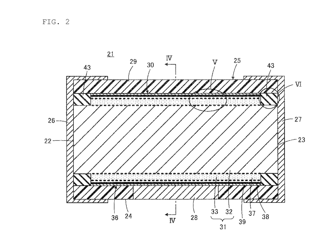
[0052]The body 25 includes a sealing member 29 containing resin, and a capacitor element 30 covered by the sealing member 29.

[0053]The capacitor element 30 includes a linear through conductor 31 made of a valve function metal. The valve function metal, of which the through conductor 31 is made, is, for example, aluminum, tantalum, niobium, titanium, or an alloy containing at least one of these materials. The through conductor 31 has a cylindrical shape in the present ...

second embodiment

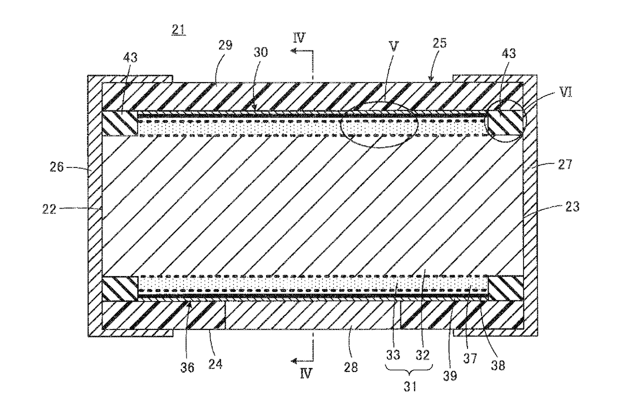
[0061]According to the present invention, as illustrated in FIG. 6, the electric insulating member 43 may be provided to fill the fine pores 34 of the porous portion 33 at a part where the electric insulating member 43 is in contact with the core portion 32. Accordingly, the porous portion 33 exists in the electric insulating member 43.

[0062]In any of the two above-described cases, the electric insulating member 43 is in contact with the core portion 32. This configuration can reduce the occurrence where a plating solution penetrates into the porous portion 33 and remains therein when, for example, wet plating is applied to form the anode terminals 26 and 27.

[0063]The sealing member 29 contains resin. The sealing member 29 may contain a filler such as alumina or silica, or a magnetic material in addition to the resin. The mechanical strength and workability of the sealing member 29 can be adjusted through this filler contained in the sealing member 29. In addition, the thermal contr...

third embodiment

[0081]The following describes a solid electrolytic capacitor 21a according to the present invention with reference to FIG. 7. FIG. 7 is a transverse sectional view taken along a central line in a front view, in which any component corresponding to that illustrated in FIG. 2 is denoted by the same reference sign, and any duplicate description thereof will not be repeated.

[0082]In the solid electrolytic capacitor 21a illustrated in FIG. 7, the body 25 includes a plurality of, for example, two of the capacitor elements 30. The two capacitor elements 30 are arranged side by side and covered by the sealing member 29.

[0083]The anode terminals 26 and 27 are formed on the end faces 22 and 23 of the body 25 to electrically connect the core portions 32 of the through conductors 31 of the respective two capacitor elements 30 with each other.

[0084]The cathode terminal 28, which is illustrated with a dotted line in FIG. 7, is provided along the bottom surface of the body 25 to electrically conne...


PUM


Abstract

A solid electrolytic capacitor that includes a capacitor element having a linear through conductor made of a valve function metal, a dielectric layer disposed on the through conductor, and a cathode-side functional layer disposed on the dielectric layer. The through conductor includes a core portion and a porous portion covering a peripheral surface of the core portion. Both end faces of the core portion of the through conductor are in contact with a pair of anode terminals on the pair of end faces of the body, respectively. A cathode terminal is electrically connected to the cathode-side functional layer.

Description

CROSS REFERENCE TO RELATED APPLICATIONS[0001]The present application claims priority to Japanese Patent Application No. 2016-069888, filed Mar. 31, 2016, the entire contents of which is incorporated herein by reference.BACKGROUND OF THE INVENTION1. Field of the Invention[0002]The present invention relates to a solid electrolytic capacitor, and particularly relates to a three-terminal solid electrolytic capacitor configured to supply electrical power via a through conductor made of a valve function metal.2. Description of the Related Art[0003]A solid electrolytic capacitor is not only used as a typical capacitor in a decoupling circuit or a power circuit, but also advantageously used as a noise filter for removing high-frequency noise.[0004]For example, WO 2005 / 015588 A discloses an interesting conventional technology to the present invention. In particular, a solid electrolytic capacitor illustrated in FIGS. 10 and 11 of WO 2005 / 015588 A is relevant. The following describes this sol...

Claims


Application Information

Patent Timeline
Patent Type & Authority Applications(United States)
IPC IPC(8): H01G9/048H01G9/07H01G9/042H01G9/15
CPCH01G9/048H01G9/042H01G9/07H01G9/15H01G9/012H01G9/14H01G9/0425H01G9/055H01G9/10H01G9/26
Inventor NOBUTA, TOMOKIFUJIMOTO, KAZUMASAYOKOKURA, OSAMU
Owner JAPAN CAPACITOR IND
Why Eureka
Try Eureka