Supercharge Your Innovation With Domain-Expert AI Agents!

Determining target distance in imaging reader

a target distance and imaging reader technology, applied in the direction of distance measurement, instruments, using reradiation, etc., can solve the problems of reducing affecting system performance and reliability, so as to improve system performance and reliability

Active Publication Date: 2010-03-16
SYMBOL TECH LLC
View PDF4 Cites 2 Cited by
  • Summary
  • Abstract
  • Description
  • Claims
  • Application Information

AI Technical Summary

Benefits of technology

The present invention is an imaging system and method for determining the distance of a target without using a rangefinder or extra sensors. The system includes an illuminator and a solid-state imager with image sensors. The illuminator generates a collimated light beam that is used for both calibration and imaging. During calibration, the illuminator illuminates a calibration target at a calibration distance and the imager captures the return light of a calibration image. The calibration distance and the calibration image size are stored in a memory for subsequent retrieval and processing. During imaging, the illuminator illuminates the target at a variable target distance and the imager captures the return light of a target image. The system calculates the target distance based on the calibration distance, the calibration image size, and the target image size. The invention enhances system performance and reliability. The imaging system includes a housing with a window and an illuminator for directing the collimated light beam through the window. The collimated light beam also acts as an aiming beam for targeting the target. The method of determining the target distance is performed by illuminating a calibration target at a calibration distance, illuminating the target at the variable target distance, and capturing the return light of the calibration image and the target image. The invention provides a novel solution for determining the target distance without using extra sensors or rangefinders.

Problems solved by technology

The design of a high performance imaging system for capturing the image of a target symbol and decoding the symbol, as well as capturing the image of a non-symbol target, presents many challenges.
However, in practice, such measures are relatively slow, add extra complexity and expense, and degrade system performance and reliability.

Method used


Image

  • Determining target distance in imaging reader
  • Determining target distance in imaging reader
  • Determining target distance in imaging reader

Examples


Embodiment Construction

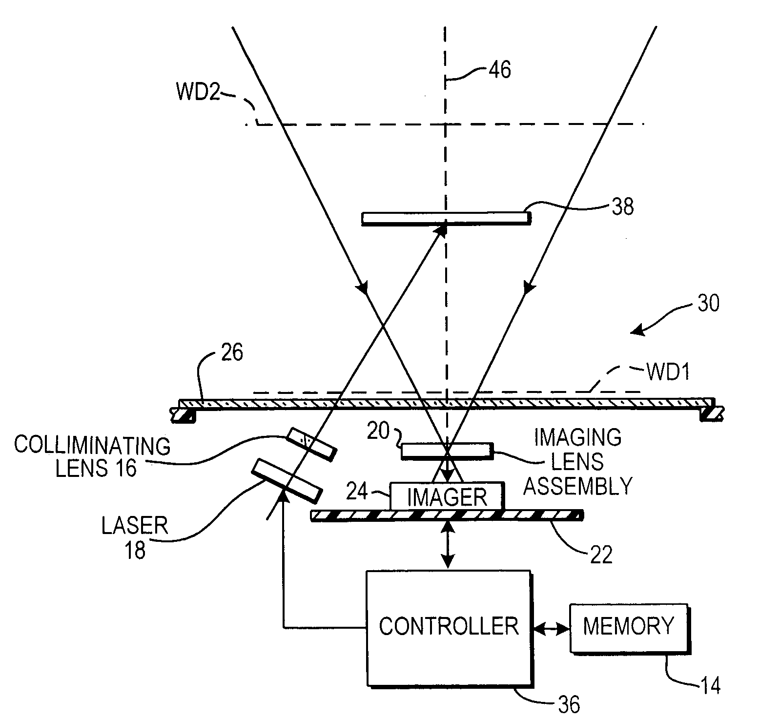
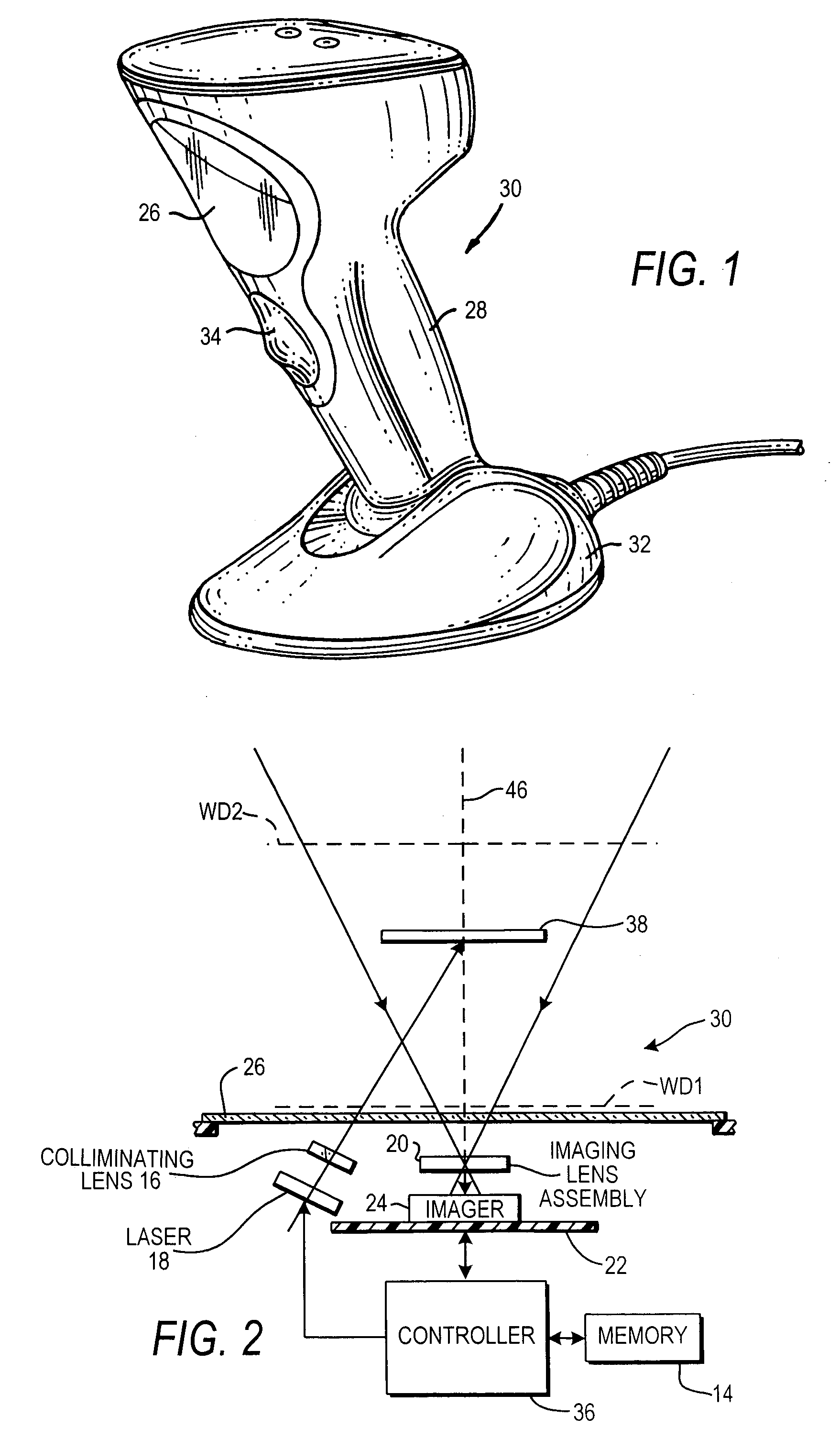
[0016]Reference numeral 30 in FIG. 1 generally identifies an imaging system or reader having a generally vertical window 26 and a gun-shaped housing 28 supported by a base 32 for supporting the imaging reader 30 on a countertop. The imaging reader 30 can thus be used in a hands-free mode as a stationary workstation in which products are slid, swiped past, or presented to, the vertical window 26, or can be picked up off the countertop and held in an operator's hand and used in a handheld mode in which a trigger 34 is manually depressed to initiate imaging of indicia to be read. In another variation, the base 32 can be omitted, and housings of other configurations can be employed.

[0017]As schematically shown in FIG. 2, an imager 24 is mounted on a printed circuit board 22 in the reader. The imager 24 is a solid-state device, for example, a CCD or a CMOS imager, and has a one- or two-dimensional array of addressable image sensors or pixels operative for capturing return light captured ...


PUM


Abstract

A target distance to a system target located at variable distances from an imaging system is determined by illuminating a calibration target at a calibration distance with a collimated light beam during a calibration mode of operation, by illuminating the system target at the variable target distance with the collimated light beam during an imaging mode of operation, by configuring the collimated light beam with a beam spot of a generally constant size during both modes of operation, by capturing return light of a calibration image size from the calibration target during the calibration mode, by capturing return light of a target image size from the system target during the imaging mode, and by determining the variable target distance based on the calibration distance, the calibration image size, and the target image size.

Description

DESCRIPTION OF THE RELATED ART[0001]Solid-state imaging systems or readers have been used to electro-optically read targets, such as one-dimensional bar code symbols, particularly of the Universal Product Code (UPC) type, each having a row of bars and spaces spaced apart along one direction, and two-dimensional symbols, such as Code 49, which introduced the concept of vertically stacking a plurality of rows of bar and space patterns in a single symbol, as described in U.S. Pat. No. 4,794,239. Another two-dimensional code structure for increasing the amount of data that can be represented or stored on a given amount of surface area is known as PDF417, as described in U.S. Pat. No. 5,304,786.[0002]These solid-state imaging systems have also been used to capture images or pictures of a non-symbol target and include an imager having a one- or two-dimensional array of cells or photosensors, which correspond to image elements or pixels in a field of view of the imager. Such an imager may ...

Claims


Application Information

Patent Timeline
Patent Type & Authority Patents(United States)
IPC IPC(8): G01C3/08
CPCG01B11/026G01C3/00G01S7/497G01S17/46G06K7/10792
Inventor WANG, DAYOUYU, MING
Owner SYMBOL TECH LLC
Features
  • R&D
  • Intellectual Property
  • Life Sciences
  • Materials
  • Tech Scout
  • Unparalleled Data Quality
  • Higher Quality Content
  • 60% Fewer Hallucinations
Learn More