
Deep discharge protection for battery packs with cell groups

a battery pack and cell technology, applied in the field of deep discharge protection for battery packs with cell groups, can solve the problems of destroying an entire battery pack, uneconomical in battery packs having many cells, and cannot be checked directly, so as to achieve the effect of reliably preventing the polarity reversal of individual cells

Active Publication Date: 2010-03-16
HILTI AG
View PDF1 Cites 1 Cited by
  • Summary
  • Abstract
  • Description
  • Claims
  • Application Information

AI Technical Summary

Benefits of technology

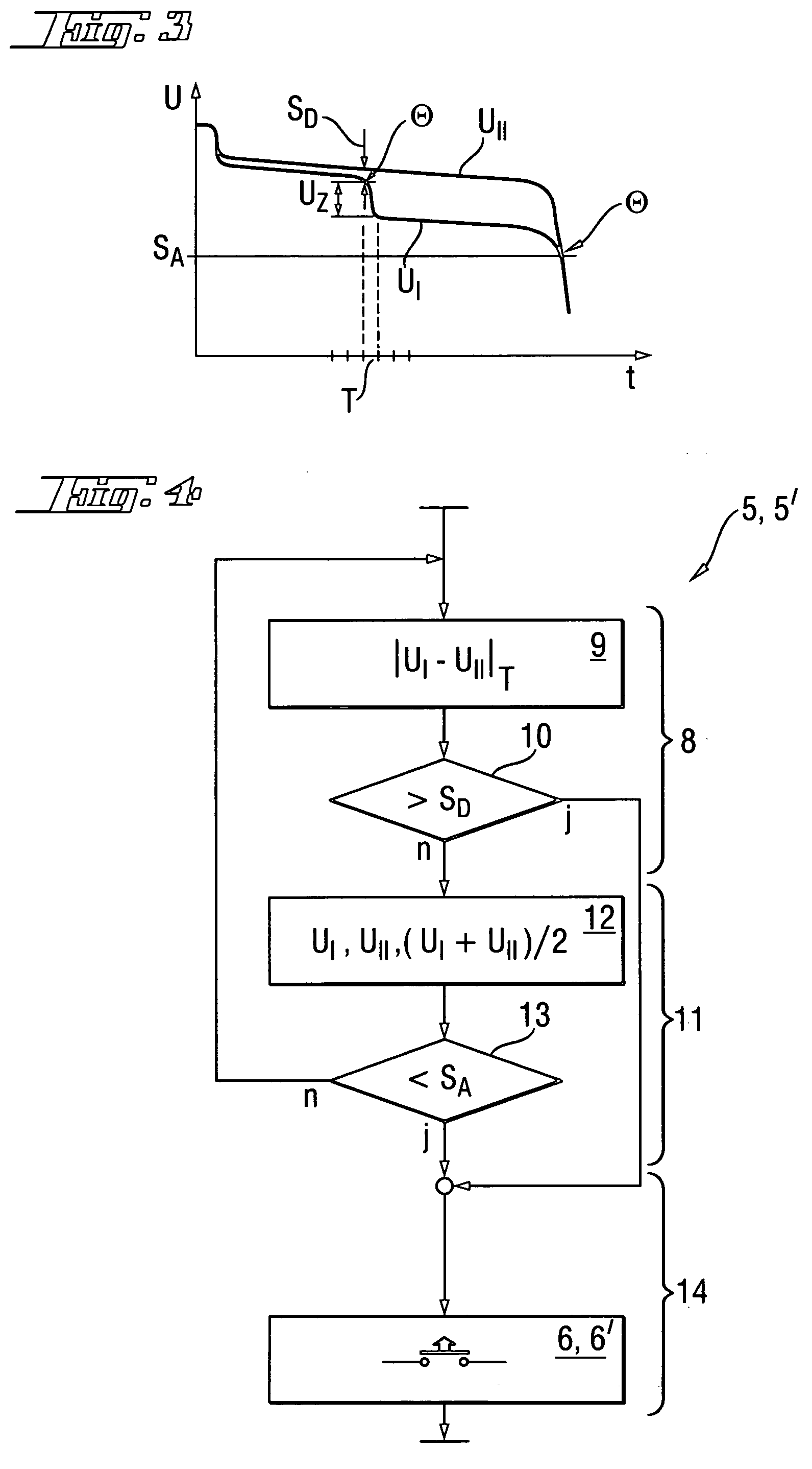
The invention provides a method for protecting battery packs from deep discharge, which can cause damage to individual cells. The method uses a difference measurement step to detect a probable reversal of polarity in an individual cell. By measuring the voltage difference between two cell groups over time, the method can reliably distinguish between a fast polarity reversal and a slow fluctuation in voltage difference. The difference threshold is set at 0.2 to 1.0 V to reliably detect incipient polarity reversal. The monitoring circuit is integrated inside the battery pack and can be produced economically. The battery pack has two cell groups connected in series, each with an identical number of cells. The invention prevents deep discharge and allows for recovery of the battery pack by reversing the polarity of the weakest cell.

Problems solved by technology

Accordingly, an individual deep discharge of one cell can destroy an entire battery pack.
However, this would be uneconomical in battery packs having many cells because of the high wiring costs.
However, individual cells cannot be checked directly in this way, so that the reversal of polarity of individual cells is difficult to prevent.
A charging process based on a charging of the battery pack that increases over time is unsuitable for a deep discharge protection during the discharge process with charging by a consumer that decreases over time.

Method used


Image

  • Deep discharge protection for battery packs with cell groups
  • Deep discharge protection for battery packs with cell groups
  • Deep discharge protection for battery packs with cell groups

Examples


Embodiment Construction

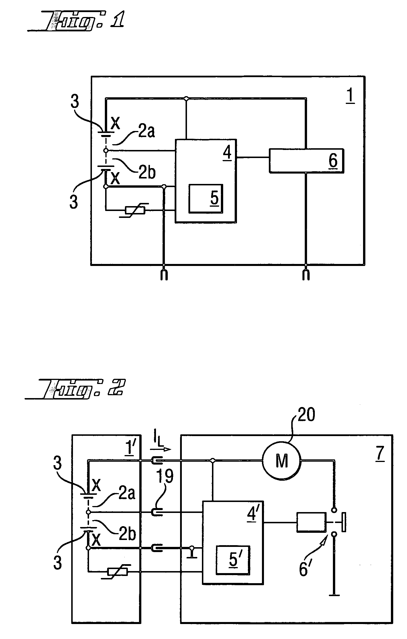
[0023]According to FIG. 1, an individual battery pack 1 with exactly two cell groups 2a, 2b which are connected in series, with each group having X=15 individual nickel-cadmium (NiCd) cells 3 with a cell voltage UZ of 1.2 V (0.5 V to 1.2 V depending on the current load IL) (FIG. 3), includes a monitoring circuit 4, which is arranged in its entirety inside the battery pack 1, in the form of a microcontroller with a program-controlled method algorithm 5 for deep discharge protection, and with a power switching element 6 in the form of an integrated semiconductor power switch.

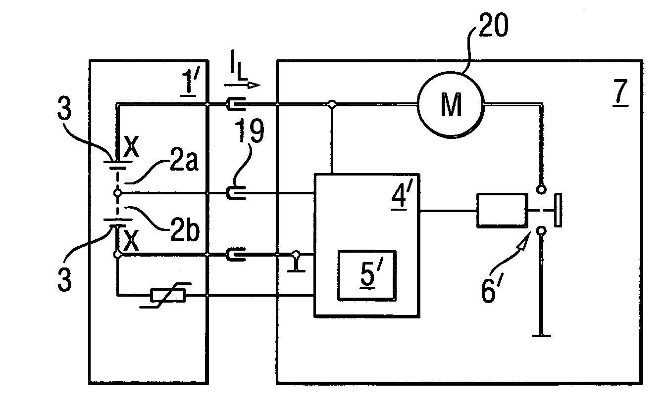
[0024]Alternatively, according to FIG. 2, a battery pack 1′ with an average voltage contact 19 which taps the intermediate voltage between exactly two series-connected cell groups 2a, 2b, with each group having X=15 individual nickel-cadmium (NiCd) cells 3 with a cell voltage UZ of 1.2 V, is connected to a 36-V battery-powered hand-held power tool 7, with an electric motor 20 as consumer. The monitoring circuit 4′...


PUM


Abstract

A method of preventing deep discharge of the battery pack (1′) with series-connected cell groups (2a, 2b) by polarity reversal of an individual weakest cell (3), includes a difference measurement step which is repeated over time for detecting an event indicative of a probable reversal of polarity in which the change over time of the voltage difference between two cell groups (2a, 2b) having identical numbers of cells is checked to determine if the change in the voltage difference has exceeded an amount corresponding to a difference threshold value which reliably distinguishes a fast polarity reversal of an individual weakest cell (3) in exactly one cell group (2a, 2b) from the slow fluctuation of the voltage difference between two cell groups (2a, 2b) during an ordinary discharge characteristic curve without polarity reversal of an individual weakest cell (3); and a battery pack (1′) and a battery-powered hand-held power tool (7) with a monitoring circuit (5′) for implementing the method.

Description

BACKGROUND OF THE INVENTION[0001]1. Field of the Invention[0002]The present invention relates to deep discharge protection for battery packs with cell groups, in particular for battery-powered hand-held power tools.[0003]2. Description of the Prior Art[0004]According to European Publication EP743736, a battery-powered hand-held power tool has a monitoring circuit that is integrated in the motor control for monitoring the charge state of the battery pack and which switches off the battery pack and / or the battery-powered hand-held power tool when a predetermined threshold value is not reached.[0005]In a deep discharge of a battery pack, the cell with the smallest capacity reverses its polarity. Accordingly, an individual deep discharge of one cell can destroy an entire battery pack. In order to prevent this, every individual cell can be checked for a deep discharge protection by a voltage monitoring device to determine whether the voltage has fallen below a threshold voltage. However,...

Claims


Application Information

Patent Timeline
Patent Type & Authority Patents(United States)
IPC IPC(8): H02H3/00
CPCH02H7/18
Inventor ZIEGLER, BERND
Owner HILTI AG
Learn More