
Portable photography studio and method of assembly

Inactive Publication Date: 2010-03-16
ADELSTEIN ALAN
View PDF24 Cites 28 Cited by
  • Summary
  • Abstract
  • Description
  • Claims
  • Application Information

AI Technical Summary

Benefits of technology

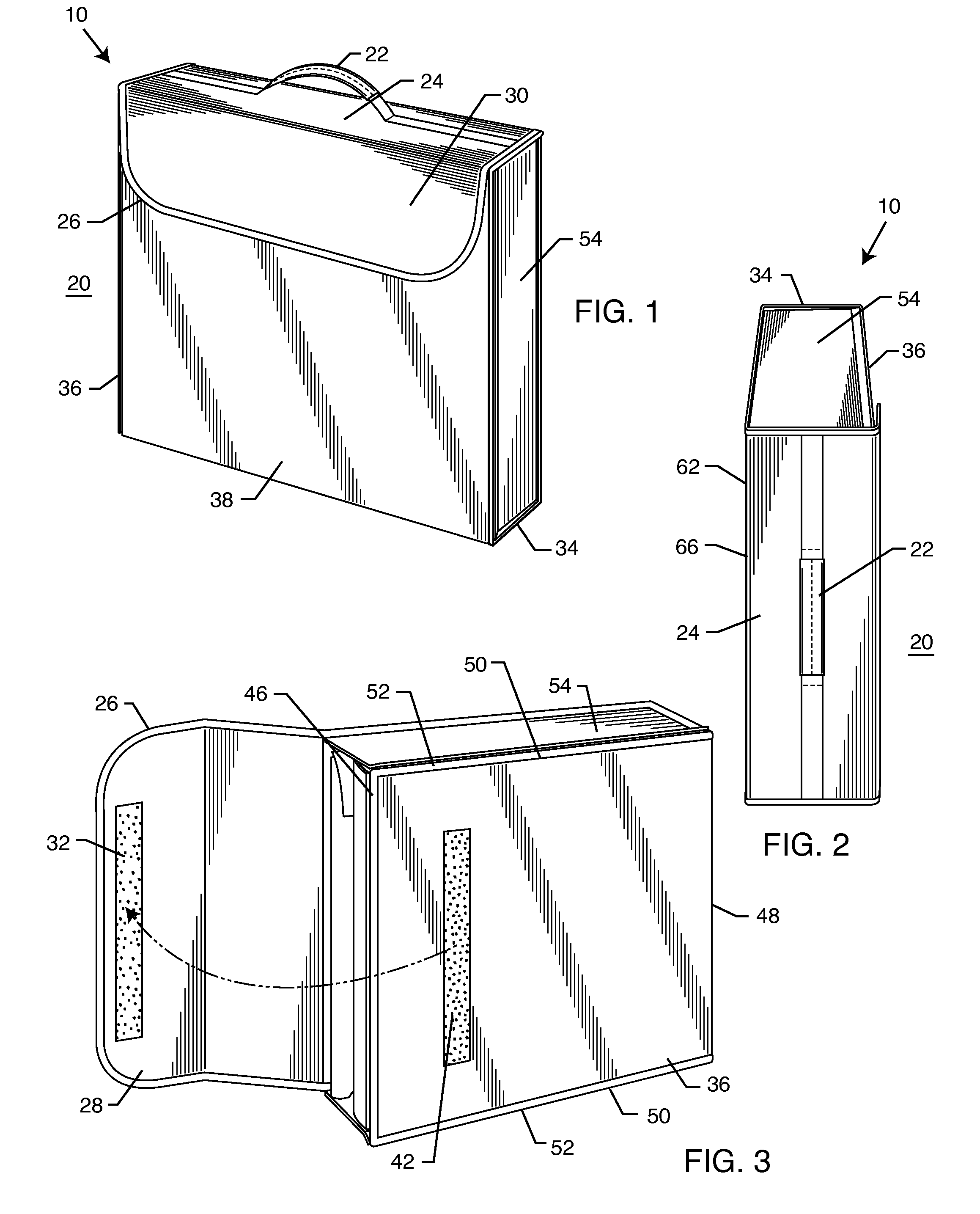
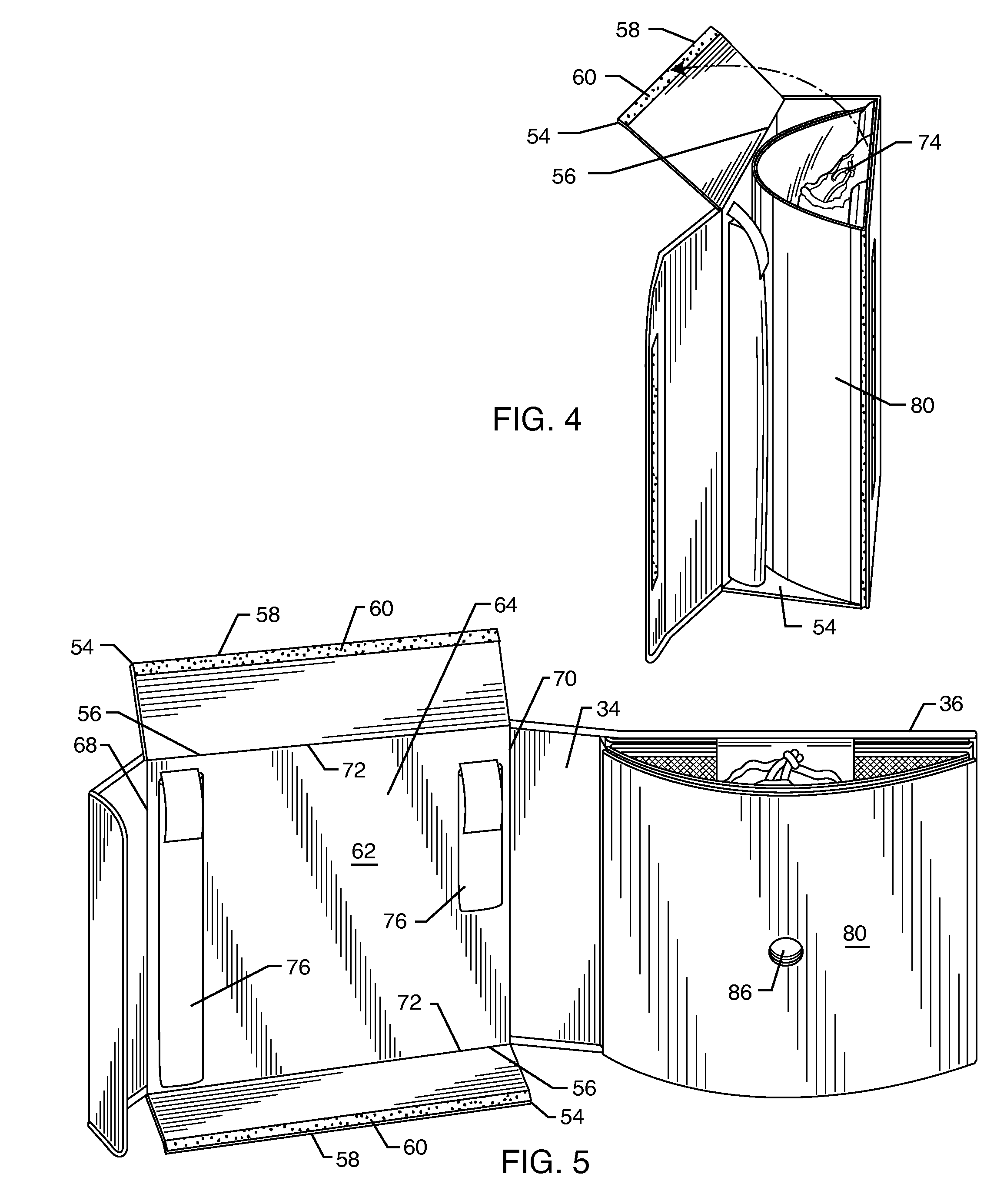
[0009]The disadvantages of known desktop photographic studios are overcome by the present invention, which, in a broad aspect, provides a compact photographic studio that may be conveniently packaged and transported in a light weight carrier that resembles a conventional suitcase. The carrier is made up of a number of panels, some of which are connected to one another by attachment means such as hook-and-loop type attachment strips, commonly known as Velcro®. While adhesive strips, zippers, buttons, hooks and the like could be used for attaching, Velcro is the preferred attachment means, which allows several of the panels to be selectively attached and / or detached from one another during assembly or disassembly of the photographic studio of the present invention.
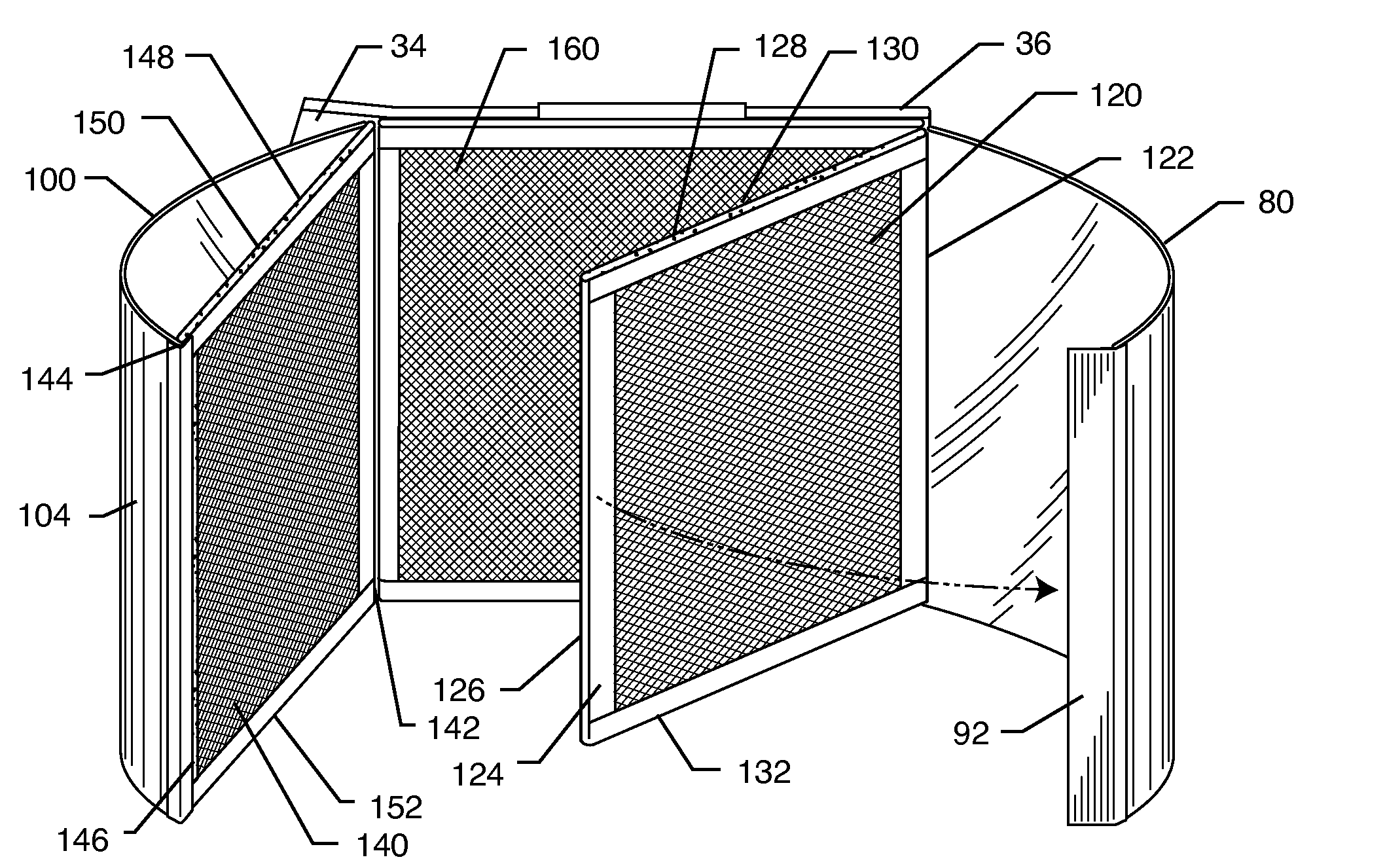
[0011]Two curved (preferably oval-shaped) reflectors are positioned on the sides of the light box and include openings into which studio quality, high output lamps may be mounted. In the preferred embodiment of the invention, the lamps are nine-volt compact fluorescent lamps that provide excellent even-color temperature and clarity.
[0012]A double sided non-reflective fabric background within the light box formed by the screens provides for excellent contrast with either light or dark objects and also creates an infinite depth of field.
[0018]Once the photography session has ended, the procedure just described is reversed and the photographic studio of the present invention is conveniently packaged into the carrier for easy transport and storage.

Problems solved by technology

Set up and take down operations were labor-intensive and time consuming.
However, there still remain the problems of packaging, assembling and transporting the photographic studio components, which may still be time-consuming and cumbersome.

Method used


Image

  • Portable photography studio and method of assembly
  • Portable photography studio and method of assembly
  • Portable photography studio and method of assembly

Examples


Embodiment Construction

[0036]In the following description of the invention, reference is made to the accompanying drawings, which form a part thereof, and in which are shown, by way of illustration, an exemplary embodiment illustrating the principles of the portable photography studio according to the present invention and how it may be practiced. It is to be understood that other embodiments may be utilized to practice the present invention and structural and functional changes may be made thereto without departing from the scope of the present invention. It should also be noted that terminology such as “top”, “bottom”, “side”, etc. are for purposes of description, clarification and illustration only and should not be interpreted as limiting the scope of the invention or to the position of any of its component parts.

[0037]A portable photography studio according to the present invention is indicated by the numeral 10 and is best illustrated in FIGS. 1, 2, and 15. FIGS. 3-12 illustrate a sequence in which ...


PUM


Abstract

A portable photography studio includes a carrier for transporting the components of the photography studio. The carrier is made up of a number of panels, several of which are detachable from the other panels. The main components of the photography studio include a pair of reflectors and three light diffusing screens, each of which has an edge attached to one of the panels of the carrier. When in use, the carrier panels may be detached and moved away from one another, allowing for the reflectors and screens to be pivoted about their attached edges and assembled in their proper positions for photographing objects. A background may also be attached to one of the panels and contained within the carrier. When the photographing is completed, the background, screens and reflectors may be pivoted back to their original positions and the carrier panels reassembled to form an enclosure holding all of the components. An accessories pouch for holding lighting devices may be included and positioned within the carrier during transport.

Description

RELATED APPLICATIONS[0001]Not applicable.BACKGROUND OF THE INVENTION[0002]1. Field of the Invention[0003]The present invention relates to the field of photography studio equipment; more specifically, the invention relates to a compact, portable photography studio that may be easily transported and carried to a desired location and quickly assembled for a photography session in a small amount of space. After the session is completed, the photography studio according to the present invention may be quickly disassembled and packaged into a compact carrier for transport to the next location or for storage.[0004]2. General Background and State of the Art[0005]Taking professional-style product still images for catalogs, internet auctions and the like used to require expensive lights, oversized light diffusion screens, a bulky camera tripod and a large dedicated space in which to set up. Set up and take down operations were labor-intensive and time consuming.[0006]With the introduction of ...

Claims


Application Information

Patent Timeline
IPC IPC(8): G03B15/00
CPCA45C9/00G03B17/568G03B15/02G03B15/06A45C3/02A45C11/38A45C2200/15A45C2013/1015G03B17/56
Inventor ADELSTEIN, ALAN
Owner ADELSTEIN ALAN
Learn More