Floor cleaning apparatus

a floor cleaning and floor technology, applied in the direction of road cleaning, carpet cleaners, cleaning equipment, etc., can solve the problem that contaminant sticking to the floor cannot be easily removed from the floor, and achieve the effect of high cleaning power, efficient removal and flotation

Inactive Publication Date: 2010-03-23
CHUGUN SABURO
View PDF20 Cites 3 Cited by
  • Summary
  • Abstract
  • Description
  • Claims
  • Application Information

AI Technical Summary

Benefits of technology

[0011]The present invention has been made in consideration of the above matter. Its object is to provide a floor cleaning apparatus, which prevents environmental pollution by wear of the polisher brush or the floor material, improves the efficiency of cleaning the floor, and cleans the floor by removing the contaminant sticking on the floor.
[0013]Since the present invention does not use a rotary polisher, it provides an environmentally friendly floor cleaning apparatus which does not cause environmental pollution by wear of the polisher brush or the floor material. Further, since the cleaning solution containing alkaline water or acid water obtained through electrolysis is pressurized and sprayed on the floor, the contaminant adhering to the floor is efficiently removed and floated, and the cleaning solution sprayed on the floor is sucked by the sucking mechanism together with the contaminant. Therefore, the floor can be cleaned efficiently with high cleaning power and the water on the floor can be removed without wiping the floor. Moreover, since the cleaning solution can be selected from alkaline water and acid water, depending on the material of the floor or the floor covering on the floor or the kind of the contaminant, efficient cleaning suitable for the kind of the contaminant can be realized without discoloring the floor or the floor covering.

Problems solved by technology

However, the contaminant sticking to the floor cannot easily be removed from the floor.

Method used


Image

  • Floor cleaning apparatus
  • Floor cleaning apparatus
  • Floor cleaning apparatus

Examples


Embodiment Construction

[0021]Embodiments of the present invention will be described below with reference to the accompanying drawings.

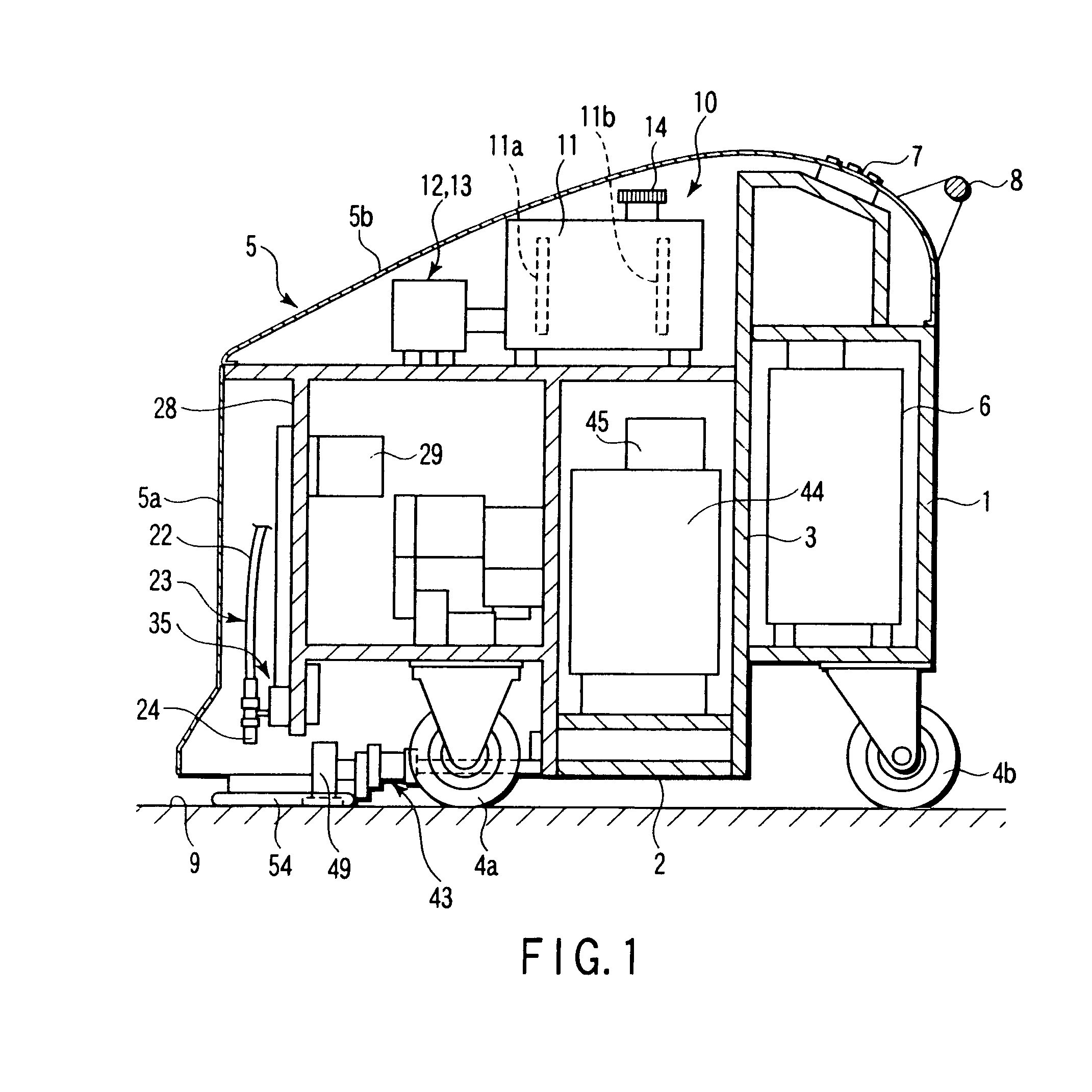
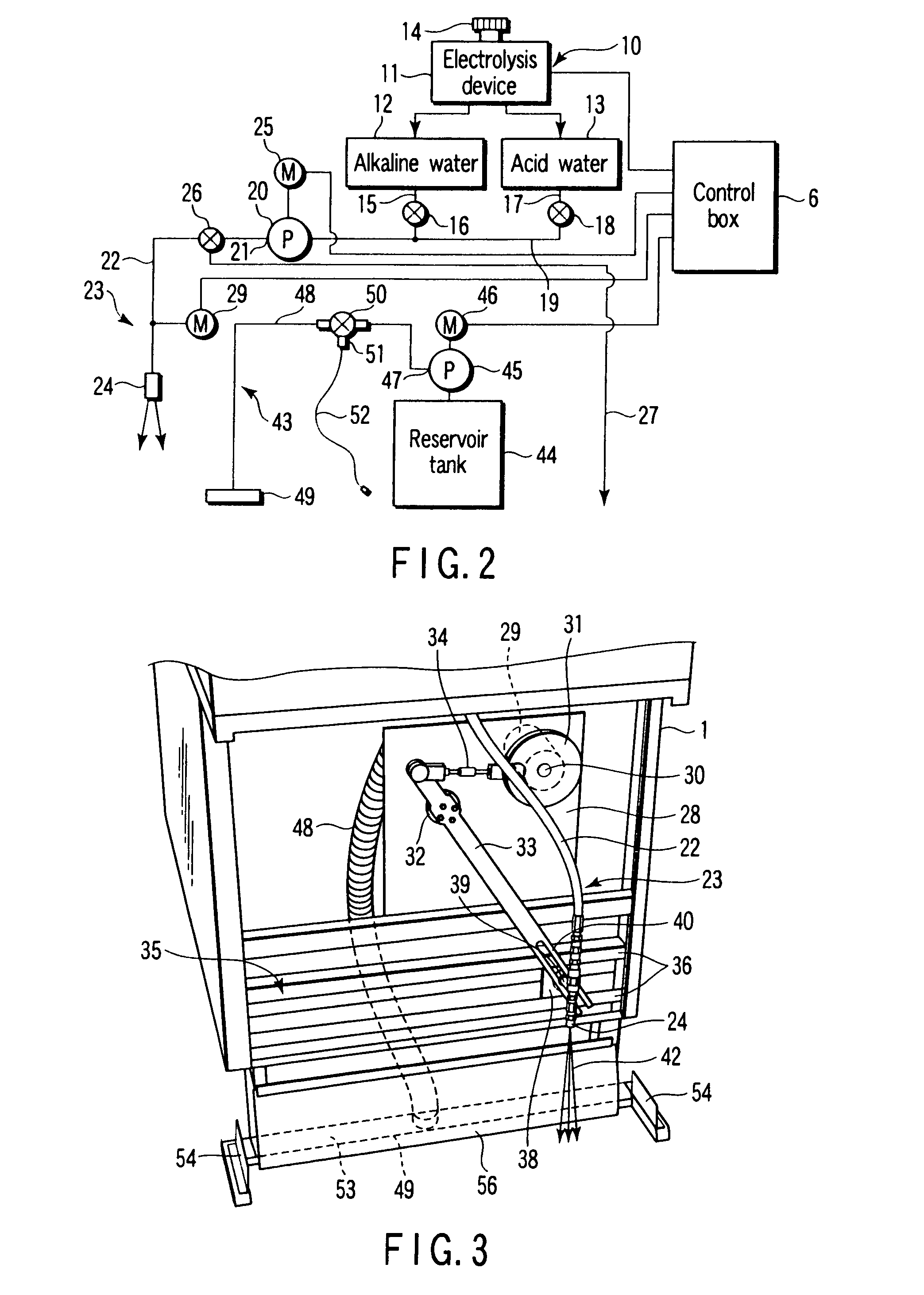
[0022]FIGS. 1 to 4 show a first embodiment of a floor cleaning apparatus. As shown in FIG. 1, the floor cleaning apparatus has an apparatus main body 1, which is driven by, for example, commercial power of alternating current at 100V. The apparatus main body 1 has a frame 3 forming a bottom portion 2. Wheels 4a and 4b are provided at four corners of a lower surface of the bottom portion 2. The wheels 4a and 4b can perform forward and backward movement by a traveling motor (not shown). The apparatus main body 1 is covered with a cover 5 including a front cover 5a and an upper cover 5b, which are removably attached. A control box 6, connected to the commercial power, is mounted on a rear portion of the apparatus main body 1. An operation panel 7, including operation buttons to be operated by an operator, is provided above the control box 6. A handle 8 fixed to the apparatus m...


PUM


Abstract

An apparatus main body having wheels and configured to run on a floor includes an electrolysis device, which electrolyzes a cleaning water to alkaline water and acid water. A pressurizing pump selectively sucks and pressurizes the alkaline water or acid water obtained by electrolysis by the electrolysis device. A spray nozzle mechanism sprays the cleaning water comprising the alkaline water or acid water pressurized by the pressurizing pump on the floor. A suction nozzle is mounted behind the spray nozzle mechanism in the apparatus main body and is opened to the floor. A suction mechanism sucks the cleaning water sprayed on the floor together with a contaminant. A reservoir tank, which is mounted in the apparatus main body, stores the sucked cleaning water together with the contaminant.

Description

CROSS-REFERENCE TO RELATED APPLICATIONS[0001]This is a Continuation Application of PCT Application No. PCT / JP2007 / 050114, filed Jan. 10, 2007, which was published under PCT Article 21(2) in Japanese.[0002]This application is based upon and claims the benefit of priority from prior Japanese Patent Application No. 2006-213661, filed Aug. 4, 2006, the entire contents of which are incorporated herein by reference.BACKGROUND OF THE INVENTION[0003]1. Field of the Invention[0004]The present invention relates to a floor cleaning apparatus to clean a floor of a large area, for example, a lobby or passageway of a building or apartment house, or underground passageway.[0005]2. Description of the Related Art[0006]A floor of a large area, for example, a lobby or passageway of a building or apartment house or underground passageway, is generally cleaned by a cleaning service staff in the following procedures. First, a weakly acid, neutral or alkaline cleaner is applied by a mop to the floor to be...

Claims


Application Information

Patent Timeline
Patent Type & Authority Patents(United States)
IPC IPC(8): A47L7/00A47L5/00
CPCA47L11/30A47L11/34A47L11/4016A47L11/4044A47L11/4077A47L11/4083A47L11/4088C02F1/4618
Inventor CHUGUN, SABURO
Owner CHUGUN SABURO
Why Eureka
Try Eureka