Powered surgical handpiece with precision suction control

a handpiece and control technology, applied in the field of powered handpieces, can solve the problems of difficult control of the suction rate of surgeons, limitation of the suction system that is integral to the handpiece, and the internal organs of patients, so as to minimize the likelihood, reduce the risk of injury, and facilitate the adjustment of positions

Active Publication Date: 2010-03-23
STRYKER CORP
View PDF7 Cites 16 Cited by
  • Summary
  • Abstract
  • Description
  • Claims
  • Application Information

AI Technical Summary

Benefits of technology

[0011]This invention relates to a new powered surgical handpiece with a valve that can readily be set to positions at which the valve only allows relatively small suction flows through the handpiece. The handpiece of this invention is further constructed so that, when the valve is in the closed state, there is no leakage suction flow through the handpiece. Still, another feature of this invention is that it is relatively simple

Problems solved by technology

Moreover, during an endoscopic surgical procedure, only relatively small portions of the patient's internal organs and tissue are exposed to the open environment.
Nevertheless, there is a limitation associated with the suction systems that are integral with these handpieces.
Specifically it is very difficult for a surgeon to regulate the suction rate, the rate at which fluid and debris are drawn away from the surgical site through the handpiece.
Nevertheless, there are some limitations associated with the suction control offered by available handpieces.
One limitation is associated with available handpieces is that it is often difficult to set the associated valve to a position in which the valve only allows a relatively small suction to be draw

Method used


Image

  • Powered surgical handpiece with precision suction control
  • Powered surgical handpiece with precision suction control
  • Powered surgical handpiece with precision suction control

Examples


Embodiment Construction

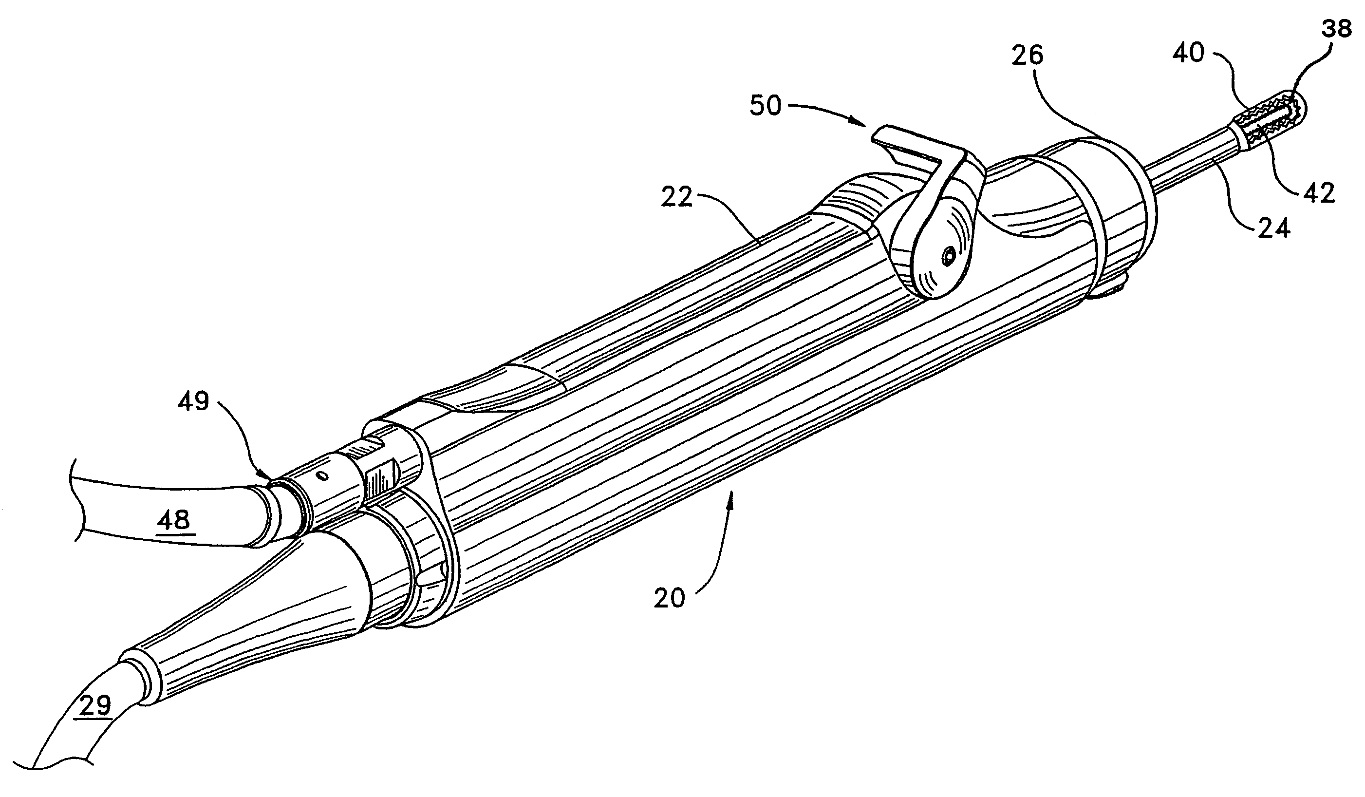
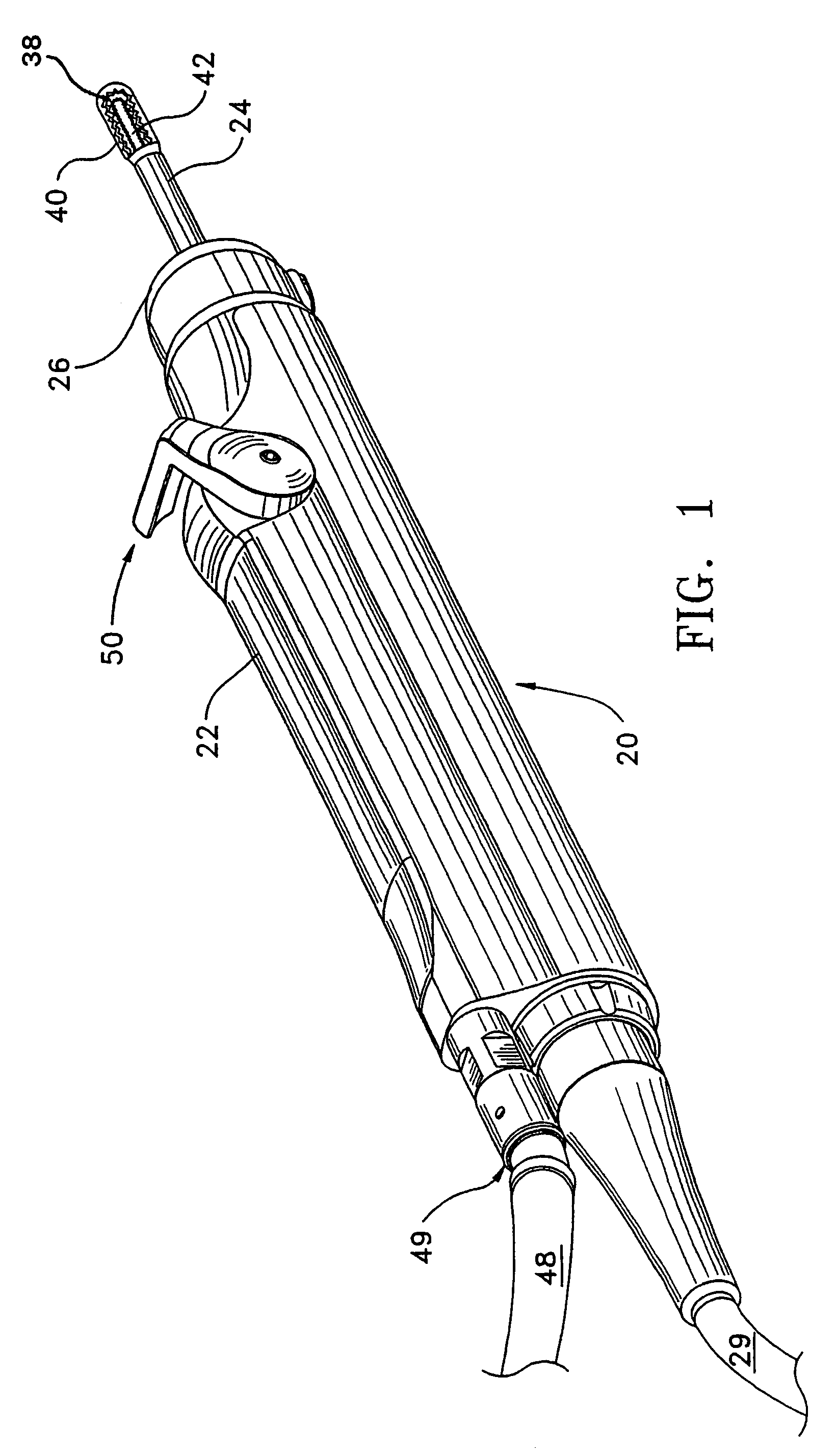
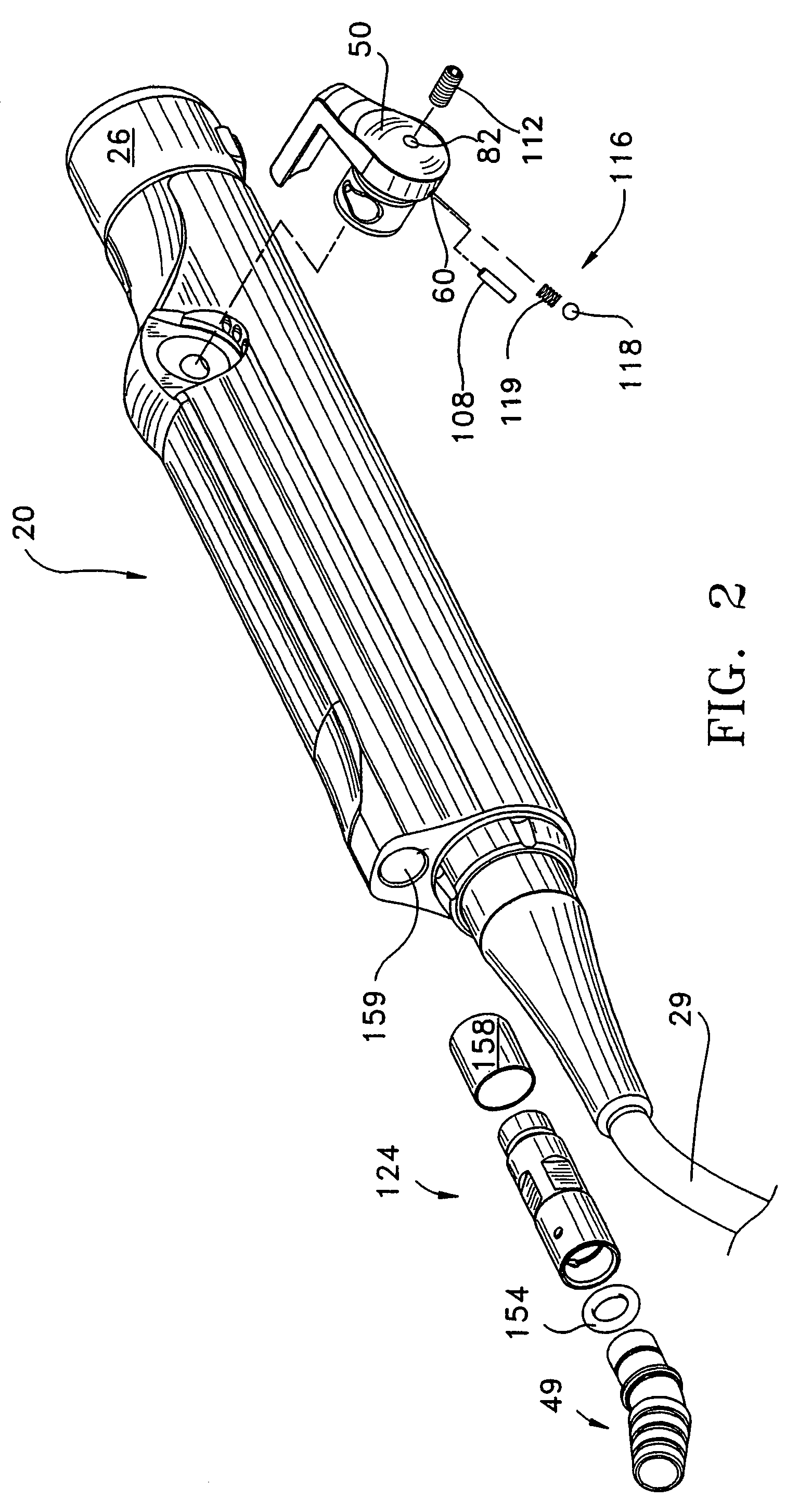
[0028]FIGS. 1 and 2 depict a surgical handpiece 20 of this invention. Handpiece 20 is designed to perform endoscopic surgical procedures though other handpieces of this invention may be designed to perform other types of surgical procedures. The handpiece 20 includes an elongated housing 22 that functions as the body of the handpiece. A complementary cutting accessory 24 is attached to the front end, also known as the distal end, of the handpiece 20. A coupling assembly 26 attached to the distal end of the housing 22 releasably couples the cutting accessory to the handpiece. A motor 28 (FIG. 3A) is located inside of the housing 22. Power is supplied to the motor from a power supply, (not illustrated), through a power cable 29 attached to the rear end, also known as the proximal end, of the housing 22.

[0029]As seen best by FIGS. 1 and 3A, the cutting accessory 24 includes inner and outer tubes 30 and 32, respectively. A static hub 34 is attached to the proximal, rear end of the outer...


PUM


Abstract

A handpiece (20) for actuating a surgical cutting accessory (24). The handpiece has a housing (22) with a bore (46) through which a suction is drawn. A valve (50) regulates the suction flow. The valve (50), formed of metal, has an barrel (60), formed of rubber, that surrounds the rotating valve stem (56). The barrel defines a non-circular openings (96) through which there is suction flow. The openings are shaped to have small diameter sections (104) that initially come into registration with the suction bore when the stem is rotated to the open state. This ensures that, when the valve is open, there is only a relatively small surgeon-selected suction flow through the handpiece. The barrel is formed with ribs (94, 106) the serve as seals between the valve and the adjacent surface of the housing. A suction fitting (49) is rotatably fitted to the proximal end of the handpiece.

Description

FIELD OF THE INVENTION[0001]This invention relates generally to powered surgical handpieces that include conduits through which suction is drawn. More particularly, this invention relates to this class of handpiece with a valve that can be set to accurately, and with nominal ergonomic effort, regulate flow through the suction conduit.BACKGROUND OF THE INVENTION[0002]Endoscopic surgical procedures are routinely performed in order to accomplish various surgical tasks. In an endoscopic surgical procedure, small incisions, called portals, are made into the patient. An endoscope, which is a device that allows medical personnel to view the surgical site, is inserted in one of the portals. Surgical instruments used to perform a specific surgical task are inserted into other portals. The surgeon views the surgical site through the endoscope to determine how to manipulate the surgical instruments in order to accomplish the surgical procedure. An advantage of performing endoscopic surgery is ...

Claims


Application Information

Patent Timeline
IPC IPC(8): A61M1/00A61B17/32
CPCA61B17/32002A61M1/0043A61M1/008A61M1/7413A61M1/84
Inventor DENG, WENJIE
Owner STRYKER CORP
Why Eureka
Try Eureka