Programmable logic device with a microcontroller-based control system

a microcontroller and control system technology, applied in the field of integrated circuits, can solve the problems of inability to use in a manner, loss of programming data of volatile control elements, and lack of flexibility of volatile control elements such as sram bits

Active Publication Date: 2010-03-23
MICROSEMI SOC
View PDF3 Cites 13 Cited by
  • Summary
  • Abstract
  • Description
  • Claims
  • Application Information

AI Technical Summary

Problems solved by technology

Volatile control elements, such as SRAM bits, lose their programming data when the PLD power supply is disconnected, disabled or turned off.
A significant limitation of the control circuits of the prior art is their lack of flexibility.
Even a very sophisticated state machine-based control system like the one in the ProASIC3 family which has a non-volatile flash memory on board which is used to parameterize its functionality is restricted to the operations dictated by its hard-wired structure and cannot be used in a manner not anticipated by its designer.
First, a PLD with prior art control logic may not work properly the first time a new product is manufactured.
Identifying the problem can be a long and arduous task, and if the debug process requires the control logic to do something outside its design and parameter limits, it can be difficult or impossible to make a correct diagnosis.
Second, the proper operation of a PLD depends greatly on the semiconductor process in which it is manufactured.
Third, there are many tasks on complicated, high-end PLDs, such as testing certain portions of the PLD not easily accessible by means of programming or external pins, that are implemented by extending the functionality of the control logic to cover those operations.
This can make the design of the control logic even more complicated and potentially error prone.
However, none of these prior art processors can be used for programming the PLD or performing other PLD internal control functions and can only be accessed as part of an end user's logic design.

Method used


Image

  • Programmable logic device with a microcontroller-based control system
  • Programmable logic device with a microcontroller-based control system
  • Programmable logic device with a microcontroller-based control system

Examples


Embodiment Construction

[0025]Those of ordinary skill in the art will realize that the following description of the present invention is illustrative only and not in any way limiting. Other embodiments of the invention will readily suggest themselves to such skilled persons.

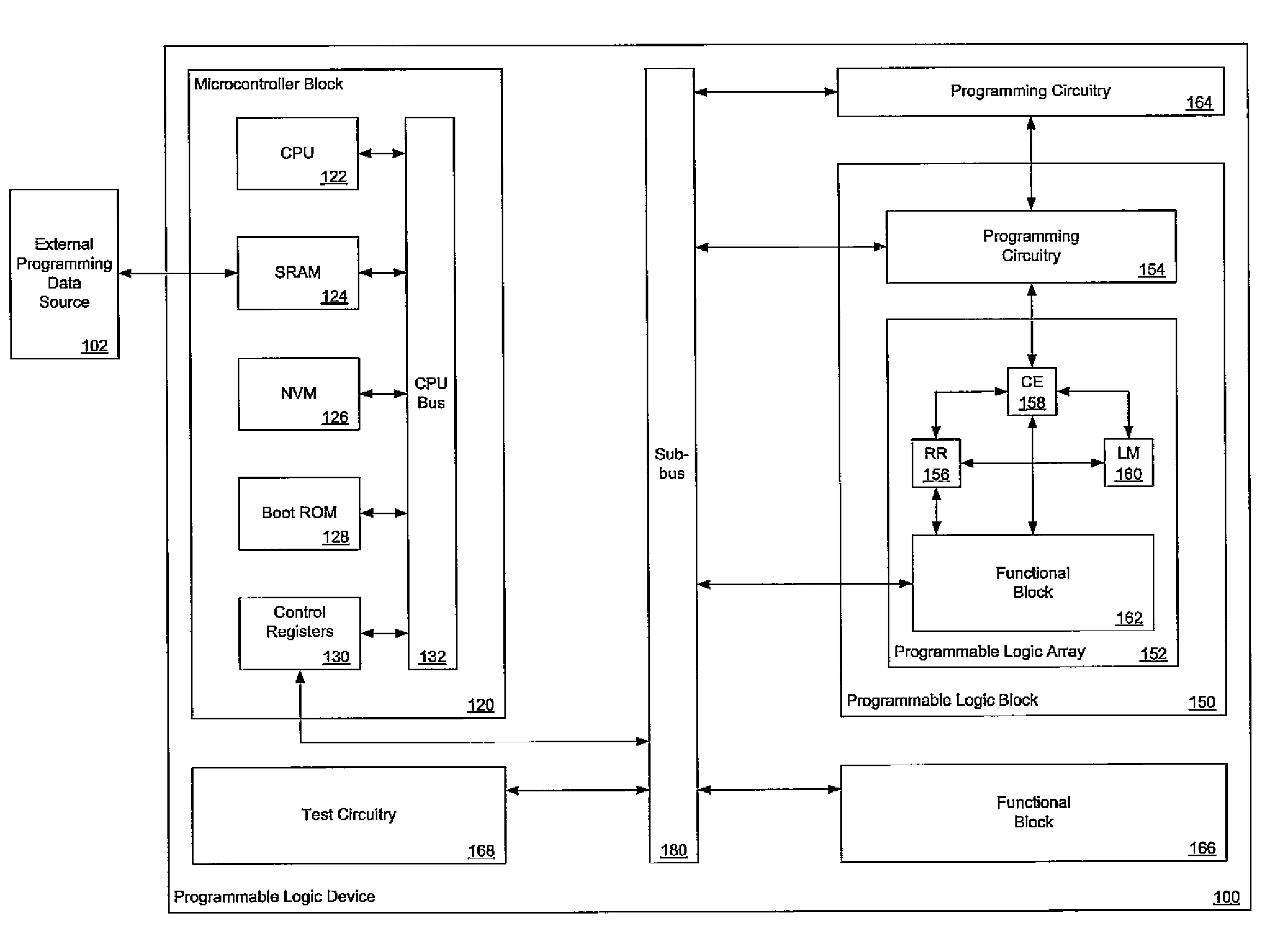
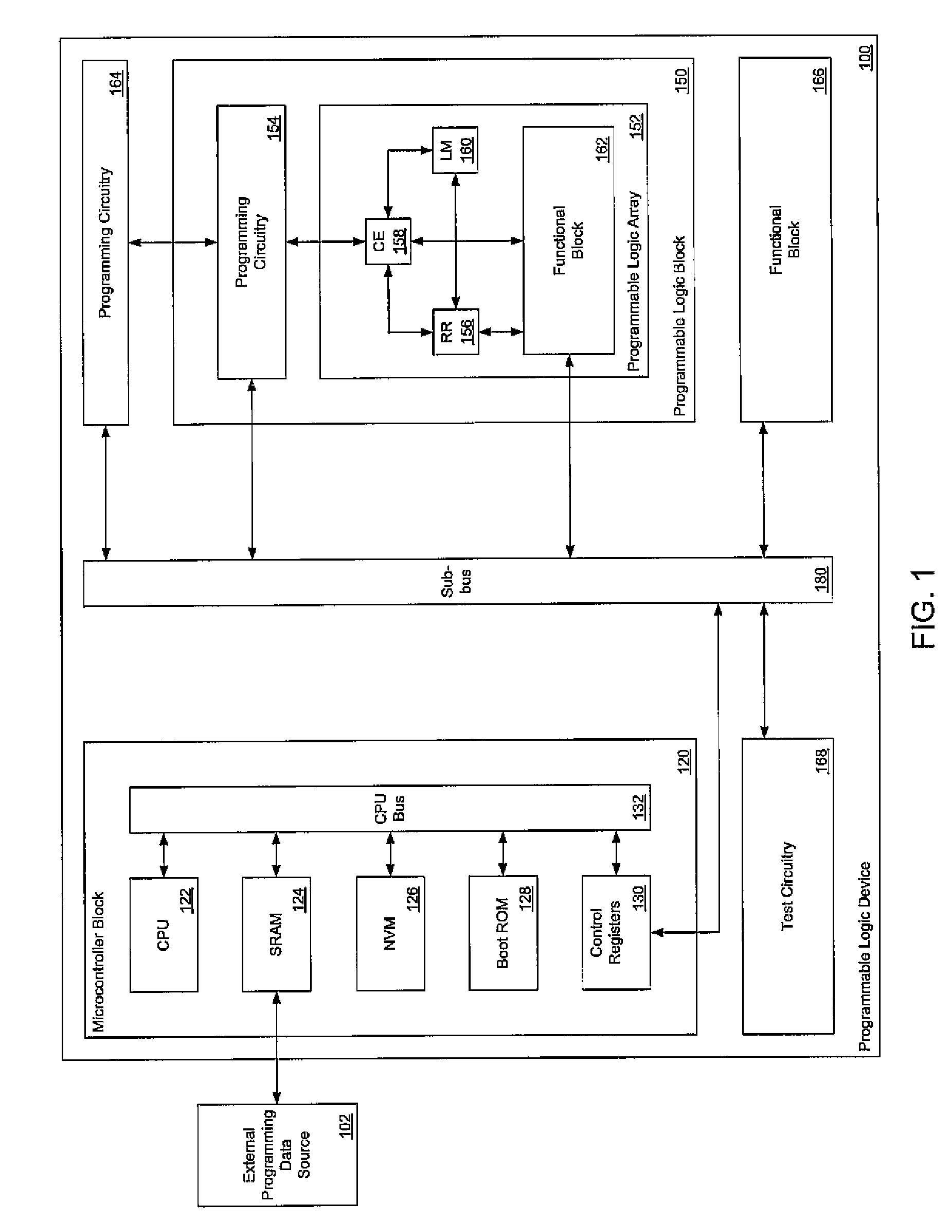
[0026]In the PLD of the present invention, a portion of the control logic is replaced by an on-chip microcontroller circuit block or system. The term microcontroller is used in a way that is consistent with the way the term is normally understood by those skilled in the art. Specifically a microcontroller is a self-contained computer which typically contains a central processing unit (CPU), an adequate amount of both volatile memory (typically flash or EEPROM) and non-volatile memory (typically SRAM) for the required tasks, and sufficient interface circuitry to interact with its environment and operate in a largely self-sufficient manner. Typically the non-volatile memory is used to store the software programs that the microcontroller r...


PUM


Abstract

A computer program product in a computer-readable medium for use in a microcontroller-based control system in a programmable logic integrated circuit device is disclosed. The computer program product comprises first instructions for initializing the device, second instructions for reading programming data from a data source external to the programmable logic integrated circuit device, third instructions for transferring the programming data into control elements internal to the programmable logic integrated circuit device. Provision is made for fourth instructions for saving at least a part of the internal logic state of the user logic programmed into the programmable logic integrated circuit device into a non-volatile memory block and for fifth instructions for restoring at least a part of the internal logic state of the user logic programmed into the programmable logic integrated circuit device from a non-volatile memory block. The programmable logic integrated circuit device, comprises a microcontroller block and a programmable logic block with programming circuitry, and has a sub-bus which couples the microcontroller block to the programming circuitry.

Description

BACKGROUND OF THE INVENTION[0001]1. Field of the Invention[0002]The invention pertains to the field of integrated circuits. More particularly, the invention pertains to programmable logic integrated circuit devices.[0003]2. Description of Related Art[0004]Programmable logic integrated circuit devices (PLDs) are known in the art. A PLD comprises a programmable logic block with any number of initially uncommitted logic modules arranged in a programmable logic array along with an appropriate amount of initially uncommitted routing resources. Logic modules are circuits which can be configured to perform a variety of logic functions like, for example, AND-gates, OR-gates, NAND-gates, NOR-gates, XOR-gates, XNOR-gates, inverters, multiplexers, adders, latches, and flip / flops. Routing resources can include a mix of components such as, for example, wires, switches, multiplexers, and buffers. Logic modules, routing resources, and other features like, for example, I / O buffers and memory blocks...

Claims


Application Information

Patent Timeline
Patent Type & Authority Patents(United States)
IPC IPC(8): H03K19/173
CPCG06F17/5054H03K19/1733G06F30/34
Inventor BAKKER, GREGORYLANDRY, JOELPLANTS, WILLIAM C.
Owner MICROSEMI SOC
Why Eureka
Try Eureka