Supercharge Your Innovation With Domain-Expert AI Agents!

Soft magnetic film and method of manufacturing same, thin-film magnetic head and method of manufacturing same, head arm assembly and magnetic disk drive

a soft magnetic film and manufacturing method technology, applied in the direction of magnetic recording, instruments, data recording, etc., can solve the problems of conventionally difficult stably achieving, difficult to stably achieve, and suffer degradation of overwrite properties, etc., to achieve stably, low coercivity, and high saturation flux density

Active Publication Date: 2010-03-23
TDK CORPARATION
View PDF22 Cites 1 Cited by
  • Summary
  • Abstract
  • Description
  • Claims
  • Application Information

AI Technical Summary

Benefits of technology

The invention provides a soft magnetic film that has high saturation flux density and low coercivity, and a method of manufacturing it. The soft magnetic film has a crystal structure that is a mixed crystal of a body-centered cubic structure phase and a face-centered cubic structure phase. The film has a low content of elements other than iron, cobalt, and nickel, and the plating current used in the manufacturing process alternates between directions. The soft magnetic film can be used in a thin-film magnetic head and a magnetic disk drive. The technical effects of the invention include stable high saturation flux density and low coercivity, improved performance of the thin-film magnetic head, and reduced size of the magnetic disk drive.

Problems solved by technology

However, if the track width is reduced, write characteristics such as an overwrite property that is a parameter indicating an overwriting capability suffers degradation.
Conventionally, however, it is difficult to stably achieve such a characteristic that the saturation flux density is 2.0 T or higher and the coercivity is 5.0×79.6 A / m or lower with a soft magnetic film made of an iron-cobalt-nickel-base alloy (such a soft magnetic film will be hereinafter referred to as an FeCoNi film), particularly an FeCoNi film formed by plating.
As previously described, it is conventionally difficult to stably achieve such a characteristic that the saturation flux density is 2.0 T or higher and the coercivity is 5.0×79.6 A / m or lower with an FeCoNi film formed by plating.
For an FeCoNi film formed by plating, however, if the iron content is increased, the amount of impurities taken into the FeCoNi film increases, and it is therefore difficult to make the saturation flux density as high as that of a bulk material.
However, the saturation flux density of the FeCoNi film decreases if the impurities content thereof increases.
However, in such an FeCoNi film, crystal grains are likely to be enlarged and the soft magnetic characteristics are thereby likely to be degraded.
In the case of forming an FeCoNi film by plating using direct currents as disclosed in JP-A 2002-134318, the soft magnetic characteristics of the FeCoNi film are likely to be degraded because the crystal grains are likely to be enlarged in the film, and furthermore, it is difficult to obtain a saturation flux density as high as that of a bulk material because a large amount of impurities are taken into the FeCoNi film.
The technique disclosed in JP-A 2000-187808 also seems to use direct currents in plating, and it is therefore difficult through this technique, too, to obtain an FeCoNi film having a saturation flux density as high as that of a bulk material.
Because of the foregoing, it is also difficult by using the technique disclosed in JP-A 2002-217029 to stably achieve such a characteristic of an FeCoNi film that the saturation flux density is 2.0 T or higher and the coercivity is 5.0×79.6 A / m or lower.
Furthermore, as can be seen from FIG. 3 of Osaka et al., it is difficult to achieve a saturation flux density of 2.0 T or higher with a cobalt-iron-nickel magnetic thin film having a composition within the range disclosed in Japanese Patent No. 2821456.

Method used


Image

  • Soft magnetic film and method of manufacturing same, thin-film magnetic head and method of manufacturing same, head arm assembly and magnetic disk drive
  • Soft magnetic film and method of manufacturing same, thin-film magnetic head and method of manufacturing same, head arm assembly and magnetic disk drive
  • Soft magnetic film and method of manufacturing same, thin-film magnetic head and method of manufacturing same, head arm assembly and magnetic disk drive

Examples


Embodiment Construction

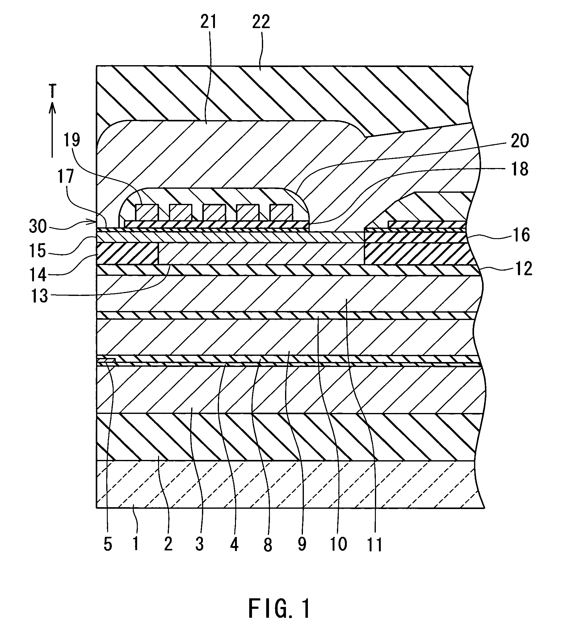
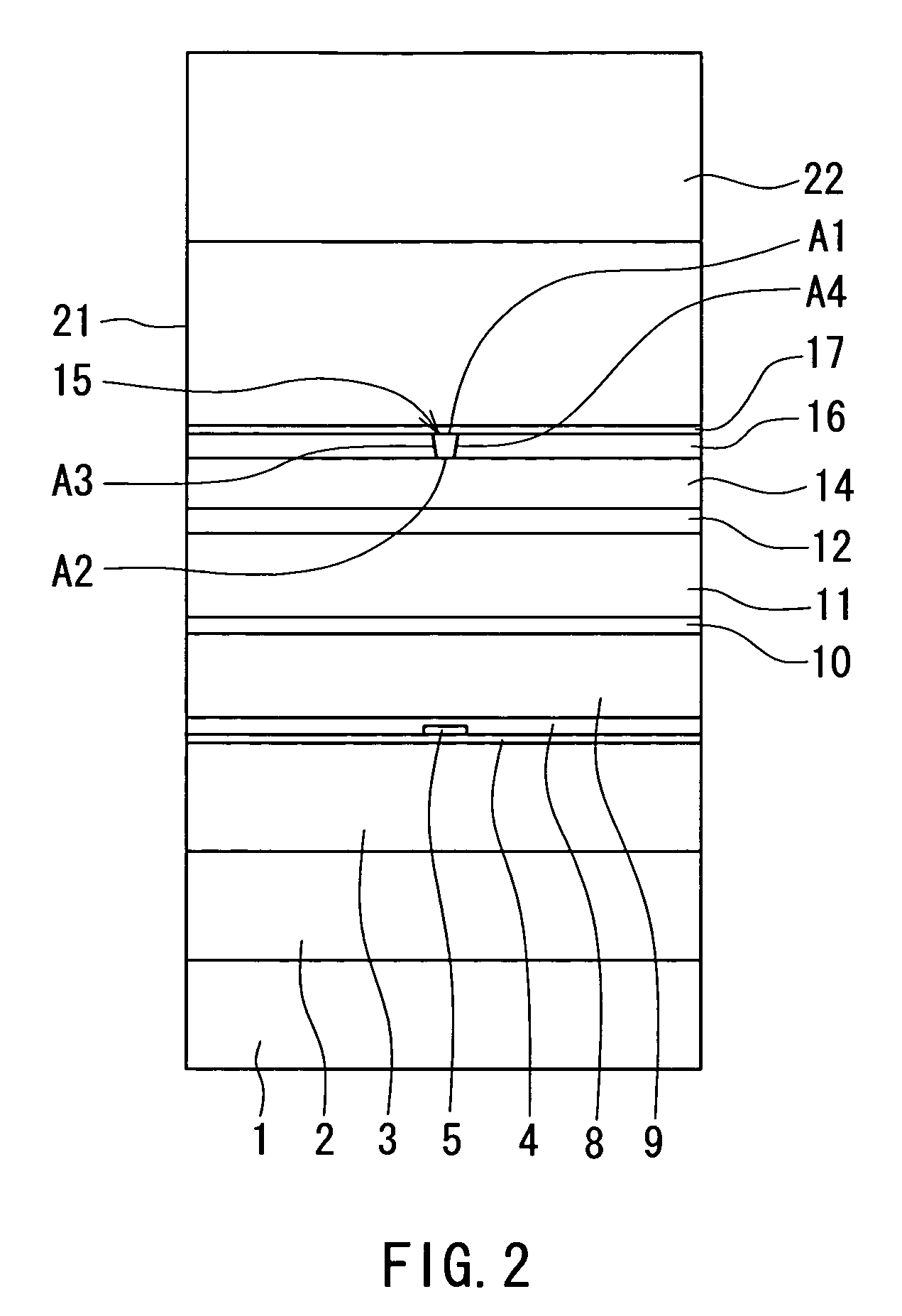
[0053]A preferred embodiment of the invention will now be described in detail with reference to the accompanying drawings. Reference is now made to FIG. 1 and FIG. 2 to describe the configuration of a thin-film magnetic head of the embodiment of the invention. The thin-film magnetic head of the embodiment is one for perpendicular magnetic recording. FIG. 1 is a cross-sectional view illustrating the configuration of the thin-film magnetic head of the embodiment. FIG. 1 illustrates a cross section orthogonal to the medium facing surface and the plane of a substrate. The arrow indicated with T in FIG. 1 shows the direction of travel of a recording medium. FIG. 2 is a front view illustrating the medium facing surface of the thin-film magnetic head of the embodiment.

[0054]As shown in FIG. 1 and FIG. 2, the thin-film magnetic head (hereinafter simply called the magnetic head) of the embodiment incorporates: a substrate 1 made of a ceramic such as aluminum oxide and titanium carbide (Al2O3...


PUM

PropertyMeasurementUnit
saturation flux densityaaaaaaaaaa
coercivityaaaaaaaaaa
widthaaaaaaaaaa

Abstract

A pole layer of a magnetic head incorporates a soft magnetic film made of an iron-cobalt-nickel-base alloy. When the total of the iron, cobalt and nickel contents of the soft magnetic film is assumed as 100 weight percent, the iron content of the soft magnetic film is within a range of 42 to 90 weight percent inclusive, the cobalt content thereof is within a range of 0 to 48 weight percent inclusive, and the nickel content thereof is within a range of 10 to 20 weight percent inclusive. The soft magnetic film has a crystal structure that is a mixed crystal of a body-centered cubic structure phase and a face-centered cubic structure phase. The soft magnetic film is manufactured by performing electroplating using a plating current whose direction is alternately switched.

Description

BACKGROUND OF THE INVENTION[0001]1. Field of the Invention[0002]The present invention relates to a soft magnetic film and a method of manufacturing the same and a thin-film magnetic head incorporating the soft magnetic film and a method of manufacturing the thin-film magnetic head, and to a head arm assembly and a magnetic disk drive each of which incorporates the thin-film magnetic head.[0003]2. Description of the Related Art[0004]Performance improvements in thin-film magnetic heads have been sought as areal recording density of magnetic disk drives has increased. A widely used type of thin-film magnetic head is a composite thin-film magnetic head that has a structure in which a write (recording) head having an induction-type electromagnetic transducer for writing and a read (reproducing) head having a magnetoresistive (MR) element for reading are stacked on a substrate.[0005]The recording systems of magnetic disk drives include a longitudinal magnetic recording system wherein sign...

Claims


Application Information

Patent Timeline
Patent Type & Authority Patents(United States)
IPC IPC(8): G11B5/31
CPCG11B5/3113G11B5/3163
Inventor YAMAGUCHI, ATSUSHINOGUCHI, KIYOSHIHIRATA, KEI
Owner TDK CORPARATION
Features
  • R&D
  • Intellectual Property
  • Life Sciences
  • Materials
  • Tech Scout
  • Unparalleled Data Quality
  • Higher Quality Content
  • 60% Fewer Hallucinations
Learn More