Vehicle-mounted stereophonic sound field reproducer

a stereophonic sound field and reproducer technology, applied in the field of vehicle-mounted three-dimensional sound field reproducing units, can solve problems such as dull distance sense, and achieve the effect of reducing crosstalk and reducing crosstalk

Active Publication Date: 2010-03-23
AUTO TECH GRP LLC
View PDF42 Cites 30 Cited by
  • Summary
  • Abstract
  • Description
  • Claims
  • Application Information

AI Technical Summary

Benefits of technology

[0020]According to this invention, even if the back and forth movement of the seat occurs, it appropriately maintains the positional relationship between the speaker-mounting parts and the head of the listener.
[0021]The three dimensional sound field reproducing unit according to this invention f

Problems solved by technology

However, since the distance from the external ears to the eardrums are largely different every individual, th

Method used


Image

  • Vehicle-mounted stereophonic sound field reproducer
  • Vehicle-mounted stereophonic sound field reproducer
  • Vehicle-mounted stereophonic sound field reproducer

Examples


first embodiment

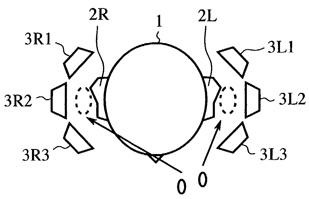
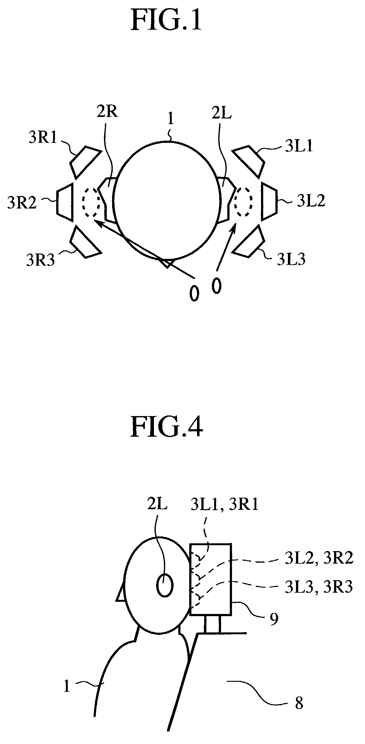
[0062]FIG. 1 is a schematic diagram showing an arrangement of speakers in a three dimensional sound field reproducing unit. Three speakers 3L1, 3L2, 3L3 and 3R1, 3R2, 3R3 are respectively disposed near each of the ears 2L, 2R of a listener 1. By means of signals to be supplied to each of the speakers, the sound fields 0 near the external ears are controlled.

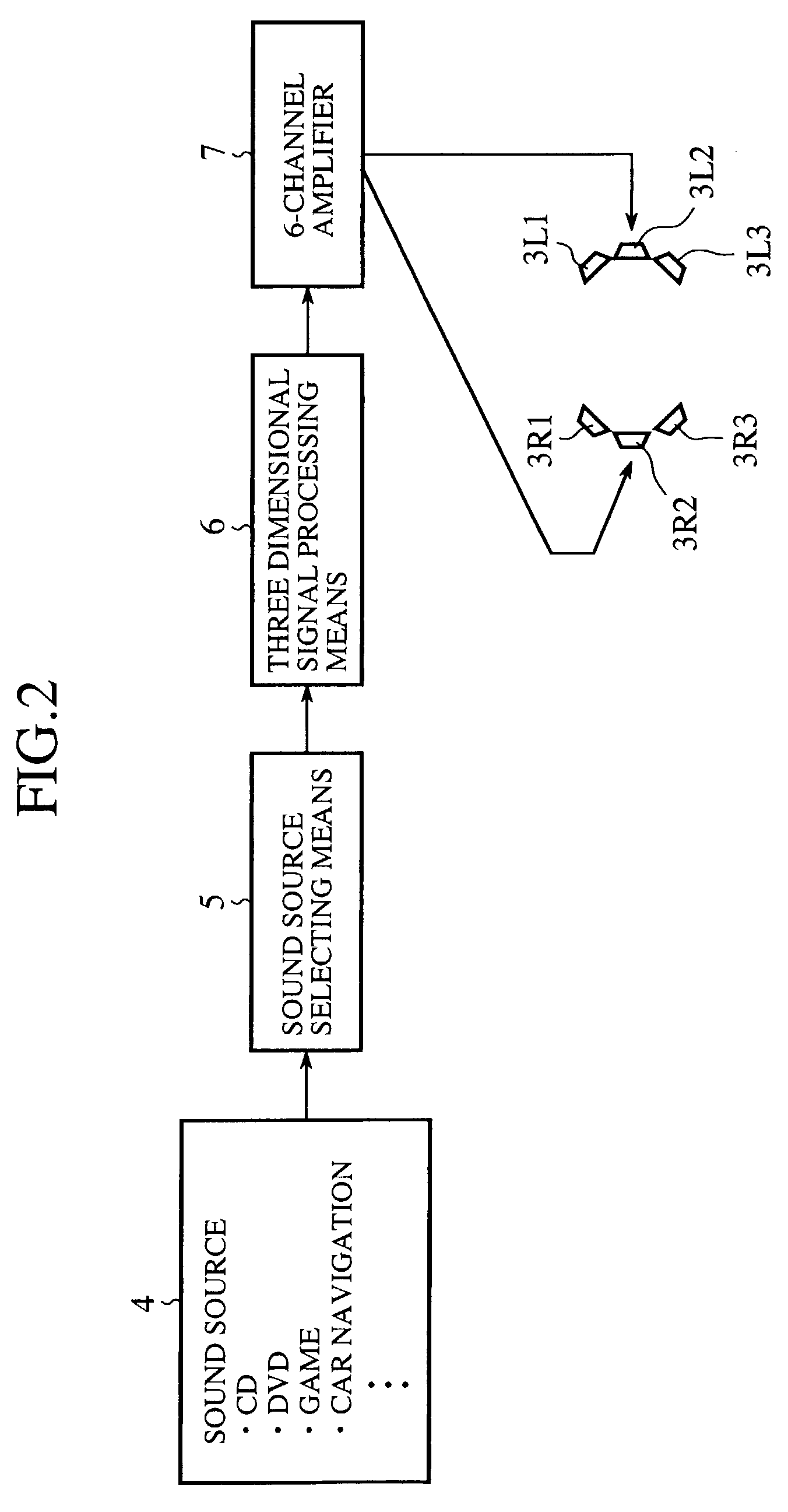
[0063]FIG. 2 shows a reproducing circuit for supplying a reproducing signal to each of the speakers 3L1, 3L2, 3L3 and 3R1, 3R2, 3R3. Referring to FIG. 2, reference numeral 4 denotes various kinds of sound source, reference numeral 5 sound source selecting means for switching the output of the sound source 4, reference numeral 6 three dimensional signal processing means, and reference numeral 7 a 6-channel (6ch) amplifier for outputting reproducing signals to six speakers 3L1, 3L2, 3L3 and 3R1, 3R2, 3R3.

[0064]The sound source 4 includes a 2-channel compact disc (CD), a 5.1-channel digital versatile disk (DVD), an amplitude modulat...

second embodiment

[0082]FIGS. 7(a) and 7(b) are diagrams showing an embodiment in which an attempt is made to reduce crosstalk between the left and right speakers and in which a pair of left and right recessed portions 9L, 9R are formed in a front of the headrest 9 so that the speakers 3L1, 3L2, 3L3 and 3R1, 3R2, 3R3 are buried deep into the head rest 9 in a position sequestered from the surface of the recessed portions 9L, 9R.

[0083]Having been arranged as above, in case the speakers are disposed on the face of the headrest 8, the distribution of sounds radiated from the speakers extends as shown in FIG. 6, thus generating a region in which a large quantity of crosstalk occurs. On the other hand, if the speakers are buried deep into the headrest 9 as with the second embodiment, the distribution of sounds radiated from the speakers will be as shown in FIG. 8, whereby the region in which a large amount of crosstalk occurs can be made smaller than the arrangement shown in FIG. 6.

[0084]As described above...

third embodiment

[0085]FIGS. 9(a) through 9(d) are diagrams showing an arrangement according to the third embodiment, wherein FIG. 9(a) is a side view, FIG. 9(b) is a side view in a state in which the speakers are in use, FIG. 9(c) is a plan view of FIG. 9(b), and FIG. 9(d) is a perspective view of FIG. 9(b). As shown in FIGS. 9(a) through 9(d), the speakers 3L1, 3L2, 3L3 and 3R1, 3R2, 3R3 are housed inside the headrest 9 so that they can be pulled out for use when necessary. The left and right speakers 3L1, 3L2, 3L3 and 3R1, 3R2, 3R3 are respectively housed in a small boxes 10L, 10R, and these boxes 10L, 10R are retractably housed into recessed portions 9L, 9R in the headrest 9 so that, when not in use, the boxes 10L, 10R are housed into the recessed portions 9L, 9R and, when in use, the boxes 10L, 10R are pulled out of the recessed portions 9L, 9R in the headrest 9.

[0086]As described above, according to the third embodiment, by housing the speakers 3L1, 3L2, 3L3 and 3R1, 3R2, 3R3 inside the boxes ...


PUM


Abstract

In correspondence with the left and right external ears of a listener occupying a seat, a three dimensional sound field reproducing unit includes at least more than two speakers disposed on a headrest on the top of a backrest of the seat, and three dimensional signal processing means which converts an output signal from a sound source into a three dimensional sound field signal for supplying it to each of the speakers. Three dimensional sound field with high accuracy and fidelity is reproduced near the external ears of the listener.

Description

TECHNICAL FIELD[0001]This invention relates to a vehicle-mounted three dimensional sound field reproducing unit capable of making a listener enjoyed perceiving a three dimensional sound field with rich presence by disposing speakers in a position close to a head of the listener inside a vehicle compartment and by controlling the sound fields near external ears of the listener.BACKGROUND ART[0002]Conventionally, many systems have been proposed in which a listener enjoys listening to a stereophonic sound field by wearing a headphone. These systems are mainly based on the principle that the sound arrived at eardrums is controlled to reproduce the original sound field. However, since the distance from the external ears to the eardrums are largely different every individual, the sound field to be localized in the front may sometimes shift to the rear, which dulls the sense of distance.[0003]In addition, there have been devised techniques in which, by utilizing speakers in a room or insid...

Claims


Application Information

Patent Timeline
IPC IPC(8): H04R5/02A47C7/72B60N2/48B60R11/00B60R11/02H04R5/027H04S1/00H04S3/00
CPCA47C7/72B60N2/4876B60N2/4882B60R11/0217H04R5/02H04R5/027B60R2011/0015B60R2011/0017B60R2011/0084B60R2011/0085H04R5/023H04R2499/13H04S1/002H04S3/00B60N2/879B60N2/885
Inventor ARAI, DAISUKEHAYAKAWA, FUJIOKITANO, TOYOAKIKOTANI, YUTAKAYAMAGISHI, YUTAKAIEDA, MASAHIRO
Owner AUTO TECH GRP LLC
Why Eureka
Try Eureka