
Equalized load distribution slips for spider and elevator

a technology for elevators and spiders, applied in the direction of transportation and packaging, braking systems, borehole/well accessories, etc., can solve the problems of limiting the length of pipe strings and exacerbate the problem of slip crushing, and achieve the effect of evenly dispersing stress

Inactive Publication Date: 2010-03-30
WEATHERFORD TECH HLDG LLC
View PDF73 Cites 15 Cited by
  • Summary
  • Abstract
  • Description
  • Claims
  • Application Information

AI Technical Summary

Benefits of technology

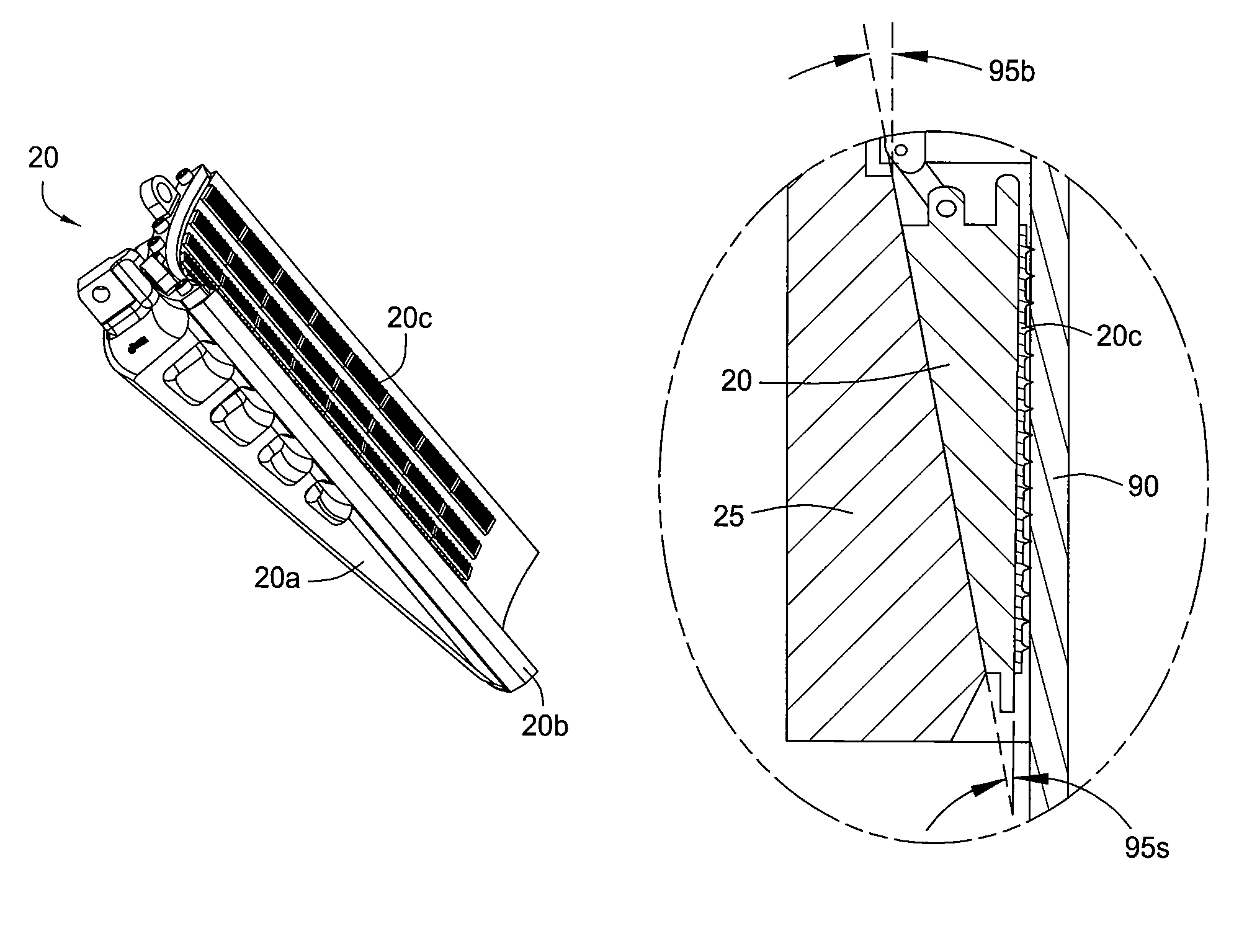
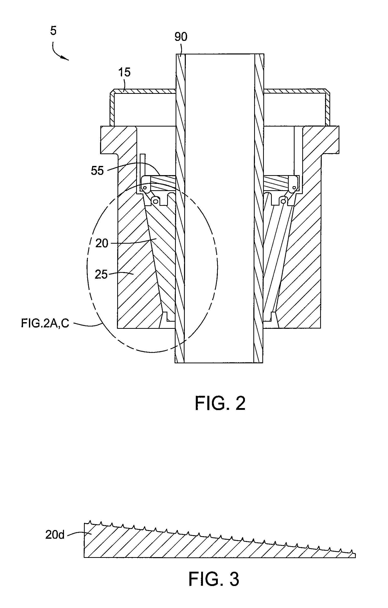
[0012]Embodiments of the present invention generally relate to an apparatus for supporting a tubular that more evenly distributes stress along the contact length of a tubular than prior art designs. In one embodiment, an apparatus for supporting a tubular is provided. The apparatus includes a slip member movable along a supporting surface in order to wedge the slip member between the tubular to be retained and the supporting surface. The contact surface between the slip member and the supporting surface is designed whereby an upper portion of the gripping surface of the slip member will initially contact the tubular, thereby distributing the forces generated by the weight of the tubular in a more effective manner.

Problems solved by technology

This slip-crushing issue limits the length of the pipe string that can be suspended by the slips.
Uneven axial distribution of the radial slip load on a pipe string exacerbates the slip crushing issue.

Method used


Image

  • Equalized load distribution slips for spider and elevator
  • Equalized load distribution slips for spider and elevator
  • Equalized load distribution slips for spider and elevator

Examples


Embodiment Construction

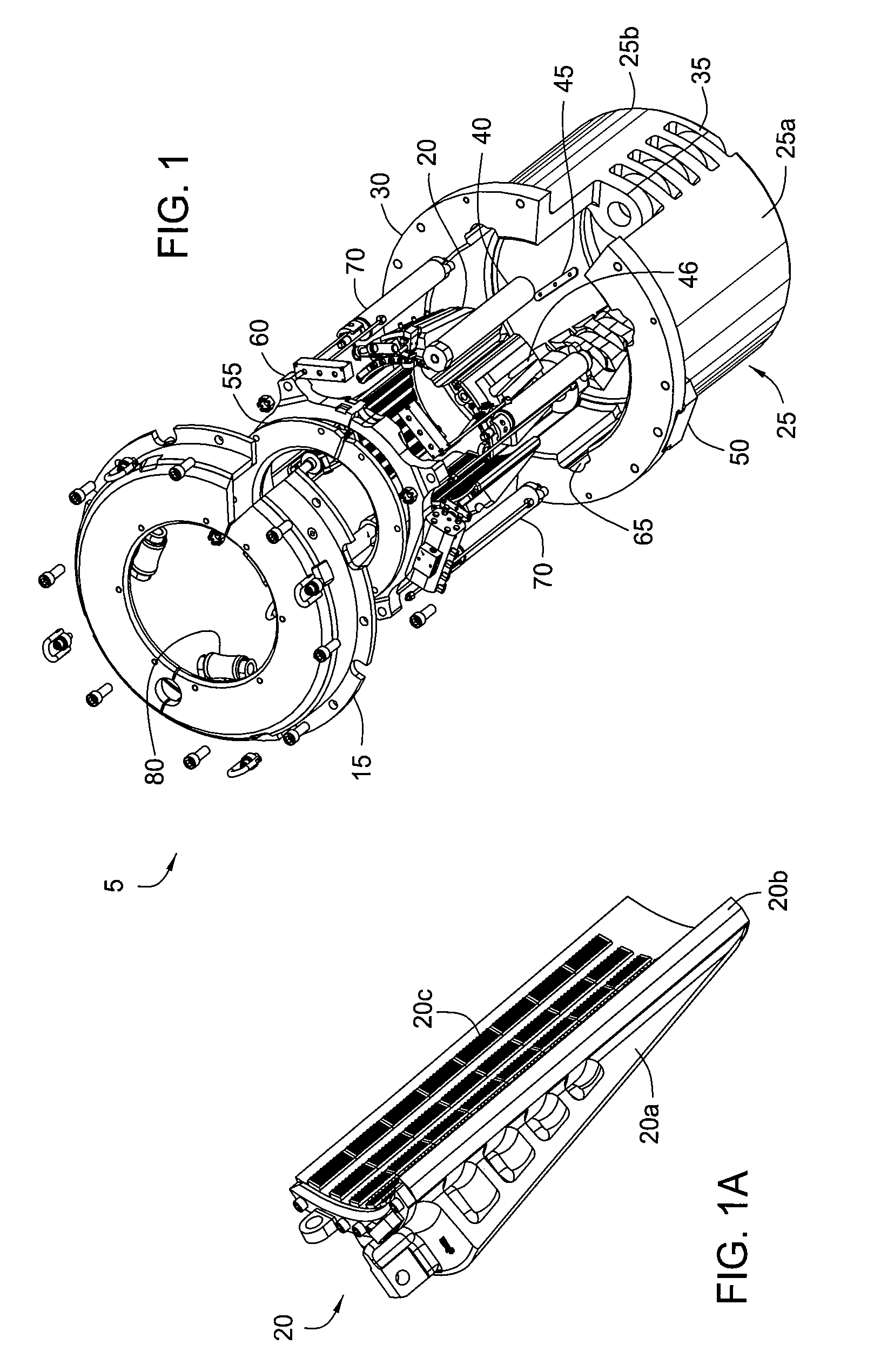
[0025]FIG. 1 is an isometric view of a gripping apparatus, according to one embodiment of the present invention. As shown, the gripping apparatus is a flush mounted spider 5 disposable within a rotary table (not shown). Alternatively, the spider 5 may be fitted for use in an elevator. Additionally, embodiments of the invention can be utilized in any well known apparatus that is dependent upon a slip member and a supporting surface, like a cone to retain the weight of a tubular string in a wellbore or at the surface of a well. Additionally, embodiments of the invention can be utilized in a top drive system used for drilling with casing. More specifically, embodiments can be used in a top drive casing make up system that grips the casing either by the inside or outside of the casing.

[0026]The spider 5 includes a body, i.e. bowl 25, for housing one or more gripping members, i.e. slips 20, and a cover assembly 15 for the bowl 25. The bowl 25 of the spider 5 is formed by pivotally coupli...


PUM


Abstract

Embodiments of the present invention generally relate to an apparatus for supporting a tubular that more evenly distributes stress along the contact length of a tubular. In one embodiment, an apparatus for supporting a tubular is provided. The apparatus includes a bowl having a longitudinal opening extending therethrough and an inner surface for receiving a gripping member. The gripping member is movable along the surface of the bowl for engaging the tubular. The apparatus is configured so that an upper portion of the gripping member will engage the tubular before the rest of the gripping member engages the tubular.

Description

CROSS-REFERENCE TO RELATED APPLICATIONS[0001]This application claims benefit of U.S. Provisional Patent Application No. 60 / 680,204, filed May 12, 2005, and U.S. Provisional Patent Application No. 60 / 689,199, filed Jun. 9, 2005. The above-referenced Applications are hereby incorporated by reference.[0002]U.S. patent application Ser. No. 10 / 207,542, entitled “FLUSH MOUNTED SPIDER”), filed Jul. 29, 2002 is hereby incorporated by reference.[0003]U.S. patent application Ser. No. 10 / 625,840, entitled “APPARATUS AND METHODS FOR TUBULAR MAKEUP INTERLOCK”), filed Jul. 23, 2003, is herein incorporated by reference.[0004]U.S. patent application Ser. No. 10 / 794,797, entitled “METHOD AND APPARATUS FOR DRILLING WITH CASING”), filed Mar. 5, 2004, is herein incorporated by reference.BACKGROUND OF THE INVENTION[0005]1. Field of the Invention[0006]Embodiments of the present invention generally relate to an apparatus for supporting a tubular.[0007]2. Description of the Related Art[0008]The handling an...

Claims


Application Information

Patent Timeline
Patent Type & Authority Patents(United States)
IPC IPC(8): E21B19/07E21B19/10
CPCE21B19/07E21B19/10
Inventor SHAHIN, DAVID
Owner WEATHERFORD TECH HLDG LLC
Learn More