Device for measuring and surgical correction imaging errors in the human eye

a technology for human eyes and imaging errors, applied in medical science, refractometers, skiascopes, etc., can solve the problems of inability to correct, unsuitable for fast conversion of measurement methods, and inability to use known methods, etc., and achieve the effect of higher spatial resolution

Inactive Publication Date: 2010-03-30
EYESIGHT & VISION
View PDF7 Cites 17 Cited by
  • Summary
  • Abstract
  • Description
  • Claims
  • Application Information

AI Technical Summary

Benefits of technology

[0007]The advantages attained with the invention consist, in particular, in that owing to the integration of the treatment laser into the device for measuring imaging errors, it is possible during surgical treatment of the eye with the treatment laser to read off the result of each individual correction step immediately and, if necessary, to improve it simultaneously. Furthermore, the mechanical and optical outlay is less than in the case of the known measuring device described at the beginning and the spatial resolution is higher, since the measurement object is scanned in an area-wide fashion.

Problems solved by technology

The evaluation of the measurement results lasts approximately 1 s. This method provides only a mean value of the defective vision, for example, existing instances of local defective vision cannot be determined individually, and therefore also cannot be corrected.
Consequently, this known method is not suitable for fast conversion of the measurement results in order to use them directly for a simultaneous surgical correction of the optics of the eye.

Method used


Image

  • Device for measuring and surgical correction imaging errors in the human eye
  • Device for measuring and surgical correction imaging errors in the human eye

Examples


Embodiment Construction

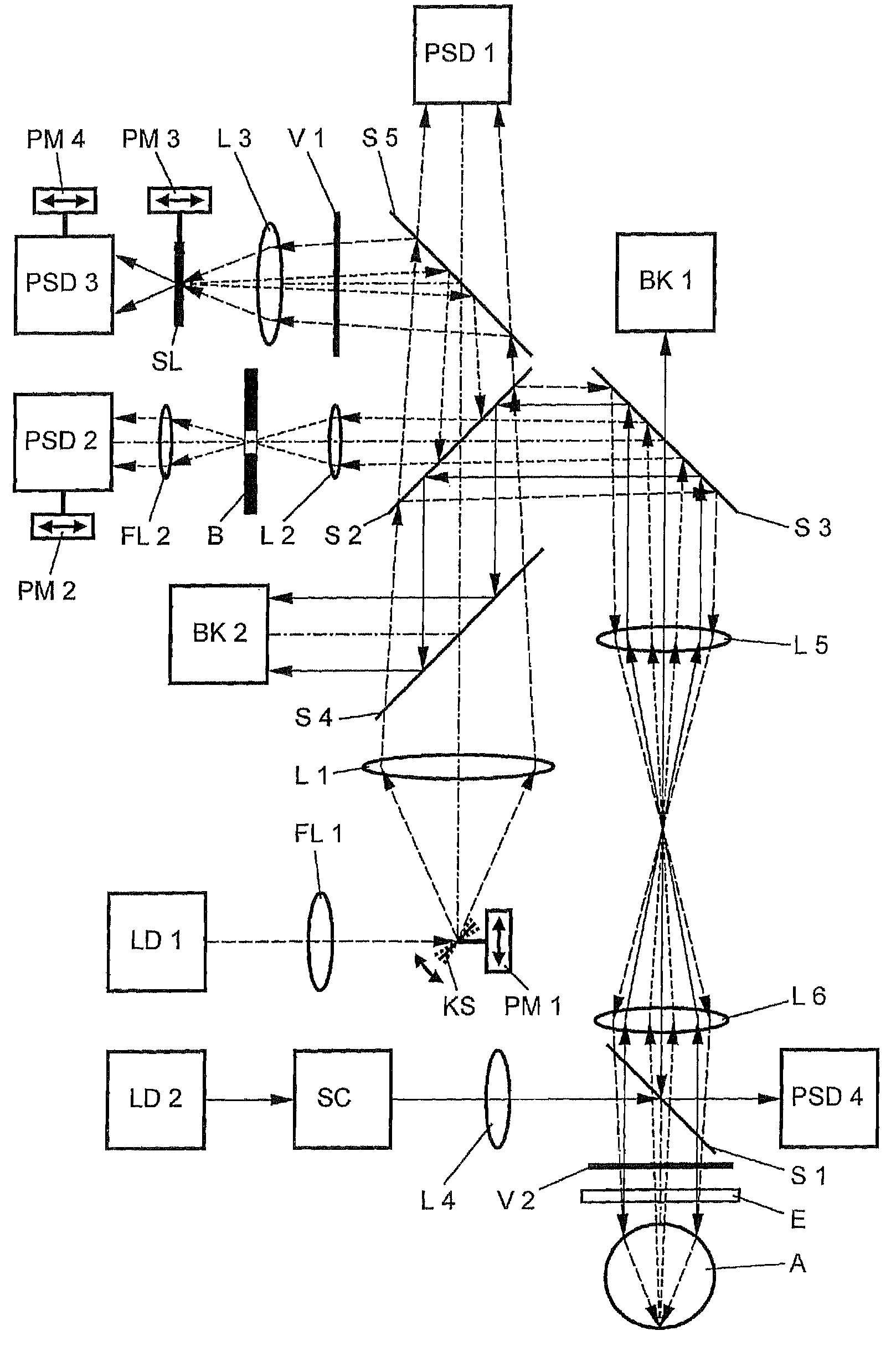
[0009]In order to measure imaging errors, including those of higher order, in the human eye A, the optical system of the latter is scanned with a measuring beam of a laser diode LD 1 in an area-wide fashion. The reflected imaging beams are measured and evaluated in order to undertake a surgical intervention on the eye A of the basis of the result. To this end, into the measuring and / or imaging beam path between the laser diode LD 1 and the eye A a beam splitter S 1 is inserted, via which beam splitter S 1 a treatment beam of a treatment laser LD 2 can be coupled in for a surgical correction of the cornea and / or the lens and / or the retina of the eye A.

[0010]For the purpose of scanning the eye A a miniature tilting mirror KS is inserted between the laser diode LD 1 and the beam splitter S 1 in the form of a 2D microscanner mirror with the aid of which the measuring beam can be deflected in two dimensions for the purpose of area-wide scanning of the eye A with frequencies of 150 Hz to ...


PUM


Abstract

The invention relates to a device for measuring imaging errors in the human eye, wherein substantial scanning of the lens of the eye with a light beam or laser diode determines the measuring accuracy of local refractive power. Measuring accuracy of locally dependent refractive power is achieved by a two-dimensionally refractable tilting mirror which is embodied in the form of a microscanner mirror with the aid of a piezomotor for positioning and by electrically controllable liquid lenses. As a result, it is possible to manufacture the measuring device as small as possible, enabling it to be integrated in to a processing laser in order to monitor the result of treatment with a laser during individual adaptation of contact lenses, intraocular lenses or surgical correction of the retina in situ and to calculate data of a required correction.

Description

BACKGROUND OF THE INVENTION[0001]The invention relates to a device for measuring imaging errors in the human eye, in the case of which the optical system of the eye is scanned with a light beam of a laser diode in an area-wide fashion, and the reflected light beams are measured and evaluated.[0002]US 2005 / 0007551 A1 discloses such a device and a method having the following method steps: measuring the imaging errors of the entire optical system of the eye and of the shape (radius of curvature) of the cornea and thus its refractive power, and calculating the imaging errors of the cornea from its refractive power, calculating the difference between the values of the imaging errors of the entire optical system of the eye, on the one hand, and of the cornea, on the other hand, storing the calculated values of the imaging errors, and converting these values into a three-dimensionally continuous display.[0003]Because of this three-dimensional distribution of the measured and calculated val...

Claims


Application Information

Patent Timeline
Patent Type & Authority Patents(United States)
IPC IPC(8): A61B3/14A61B3/10
CPCA61B3/103A61F9/008A61F2009/00846A61F2009/00848A61F2009/00855A61F2009/00863A61F2009/0087A61F2009/00872A61F2009/0088A61F2009/00897
Inventor HEIBERGER, KURT
Owner EYESIGHT & VISION
Why Eureka
Try Eureka