
Radially mobile bearing for a shaft pertaining to a steering system

a technology of rotating bearings and steering systems, which is applied in the direction of steering controls, bearings, power driven steering, etc., can solve the problems of complex design measures in terms of production engineering and inability to compensa

Active Publication Date: 2010-03-30
ROBERT BOSCH AUTOMOTIVE STEERING
View PDF15 Cites 12 Cited by
  • Summary
  • Abstract
  • Description
  • Claims
  • Application Information

AI Technical Summary

Benefits of technology

The patent describes a bearing system for a gear housing that uses a radially movable bearing and a support element made of elastomer material. The support element is inserted into a gap between the outer ring of the bearing and the receiving element in the gear housing. The support element acts as a pivot bearing, holding the outer ring in a way that it does not have any metal contact with the receiving element. The support element is fixed in a press fit or form fit on the outer ring and the receiving element. The use of elastomer material simplifies assembly and protects against relaxation. The support element can be formed in a single piece with an inner ring that surrounds the outer ring or the bush of the bearing. The support element and inner ring can have a structural reinforcement, such as metal lattice or fiber reinforcement. The support element can have concave outer surfaces and the inner ring can have areas with greater wall thicknesses to act as a noise-damping stop. The bearing system is suitable for use in electrical actuators and can be produced from thermoplastic or elastomer materials. The patent also mentions different types of bearings that can be used for the movable bearing.

Problems solved by technology

This leads to noise, in particular when the direction of rotation of the shafts changes, for instance in steering gears when there is a change in the direction of travel.
This design measure is complex in terms of production engineering and is not able to compensate wear in the denticulation.

Method used


Image

  • Radially mobile bearing for a shaft pertaining to a steering system
  • Radially mobile bearing for a shaft pertaining to a steering system

Examples


Embodiment Construction

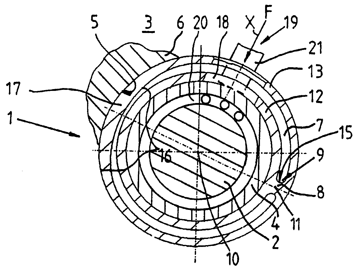
[0019]FIG. 1 depicts in a schematic section through a mount 6 or housing of a gear 3, in which a radially movable bearing 1 that, for bearing a shaft 2, bears the one worm (not shown) of the gear 3 embodied as a worm wheel gear and to which the shaft 2 is connected rotation-fast. The radially movable bearing 1 is arranged in a receiving element 5 of the gear 3 and is acted upon by a partially depicted pressing device 19, more precisely, by a thrust member 21, in the radial direction x with a pressing force F. The worm on the shaft 2 is pressed onto denticulation of a worm wheel (not shown) by the force F.

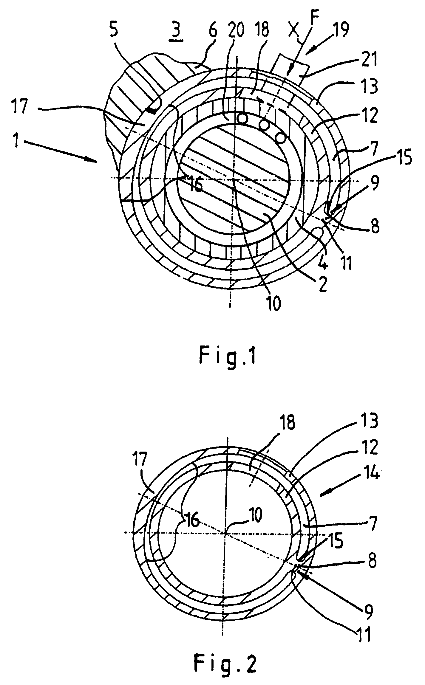
[0020]The radially movable bearing is embodied as a roller bearing 20, an outer ring 4 of the roller bearing 20 being held in an inner ring 12 of a pivot bush 14 (see FIG. 2) and being made of a material with elastomer behavior. The inner ring 12 is connected via a single support element 8 to a support ring 13 that surrounds the inner ring 12. In the exemplary embodiment depicted in...


PUM


Abstract

A radially movable bearing for a shaft of a gear in a steering system includes a bush or outer ring that is supported in a receiving element of a mount or housing for the gear. In order to create a radially flexible bearing for the shaft of the gear, which movable bearing enables quiet operation for the entire service life of the gear, the outer ring or the bush is held by at least one support element that is inserted in a gap between the receiving element and the outer ring, and that is made of a material with elastomer behavior.

Description

BACKGROUND OF THE INVENTION[0001]The invention relates to a radially movable bearing for a shaft of a gear in a steering system.[0002]In gearboxes of steering systems, in particular, in rack-and-pinion gears or worm gears, shafts having driving wheels such as pinions or worms are borne in one fixed bearing and in one radially movable bearing. The movable bearing has the freedom to permit the driving wheel to roll on the driven wheel or a rack using a pressing device. The pressing device also compensates wear between the driving wheel and the driven wheel or the corresponding denticulation between the wheels. However, in order to enable low-friction adjustment of the movable bearing, in terms of design, transverse clearance should be provided, relative to the amount of freedom, between the outer ring of the movable bearing and a receiving element for the movable bearing in a gear housing of the gear. This leads to noise, in particular when the direction of rotation of the shafts chan...

Claims


Application Information

Patent Timeline
Patent Type & Authority Patents(United States)
IPC IPC(8): F16C27/06B62D1/16F16C33/02
CPCB62D3/12B62D5/0409F16C27/06F16C2326/24F16C2361/61
Inventor SCHUST, ACHIM
Owner ROBERT BOSCH AUTOMOTIVE STEERING
Learn More