Iron core linear motor having low detent force with high power density

a linear motor and low detent force technology, applied in the direction of electrical apparatus, dynamo-electric machines, cooling/ventilation arrangements, etc., can solve the problems of inability to achieve precise force- or force/path measurement, detent force occurs, and it is difficult to achieve a compact type of linear motor construction

Inactive Publication Date: 2010-03-30
JENNY ALOIS
View PDF19 Cites 3 Cited by
  • Summary
  • Abstract
  • Description
  • Claims
  • Application Information

AI Technical Summary

Benefits of technology

[0019]It is an object of the present invention to provide an iron core linear motor of the type initially mentioned, in which the above-mentioned problems are largely avoided, and which has in particular a low detent force even in the inlet / outlet region, allows a compact type of construction and can be produced at a favourable cost.
[0023]An iron core linear motor according to the invention has substantially the same manufacturing costs as a conventional iron core linear motor without measures against the detent force, because no costly active devices are necessary and the manufacture of the stator does not become more complicated.

Problems solved by technology

However, the use of iron core coils has the considerable disadvantage, compared with air gaps, that a detent force occurs, the so-called “cogging”, a phenomenon which is also known from rotating electric motors.
A further disadvantage of the detent force is the adulterated relationship between current consumption of the motor and effective propulsive force; this is not linear and therefore the motor can not be used for precise force- or force / path measurement.
However, it is difficult to achieve a compact type of construction of the linear motor with this development.
This solution is only suitable for runners which move on a long stator.
The additional active element is, in addition, complex and therefore expensive.
Such a type of construction is complex and, accordingly, expensive.
This leads to destructive interference of the detent forces, and hence to a reduction of the detent forces.
However, the detent force problem is not solved thereby in the inlet / outlet region.
This type of construction has the disadvantage that the coils can not be simply be turned over the iron poles, but rather must be wound around them in a complicated manner.

Method used


Image

  • Iron core linear motor having low detent force with high power density
  • Iron core linear motor having low detent force with high power density
  • Iron core linear motor having low detent force with high power density

Examples


example embodiment

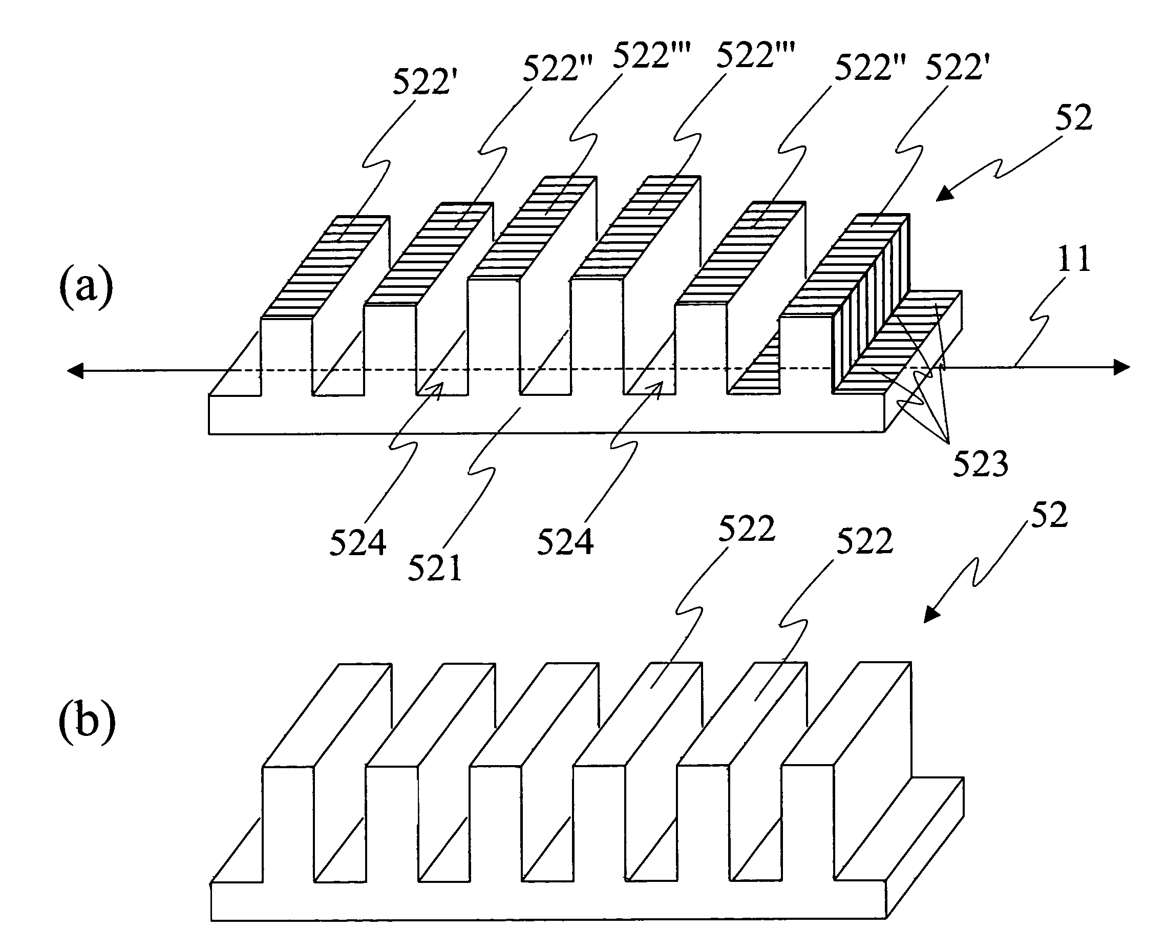
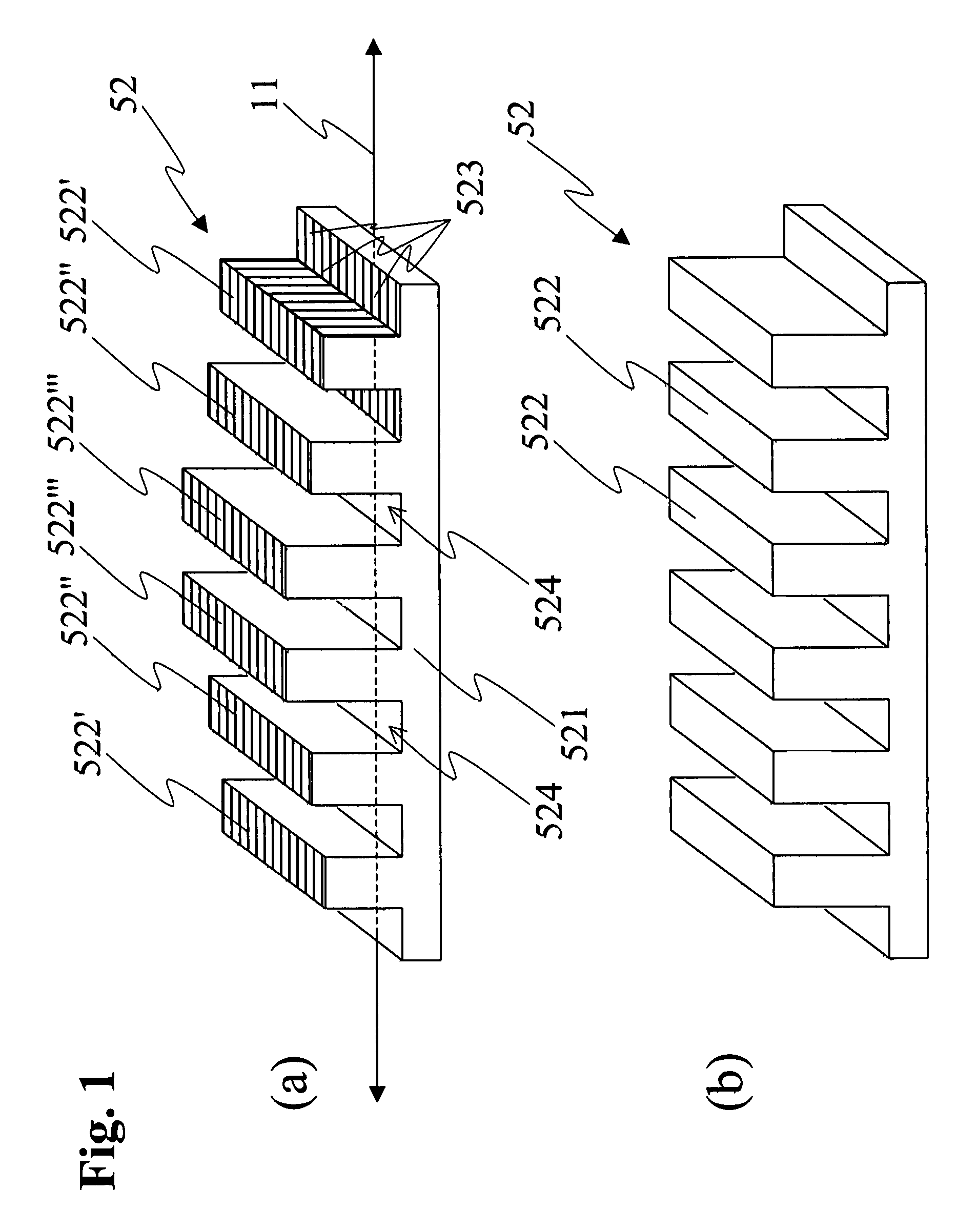
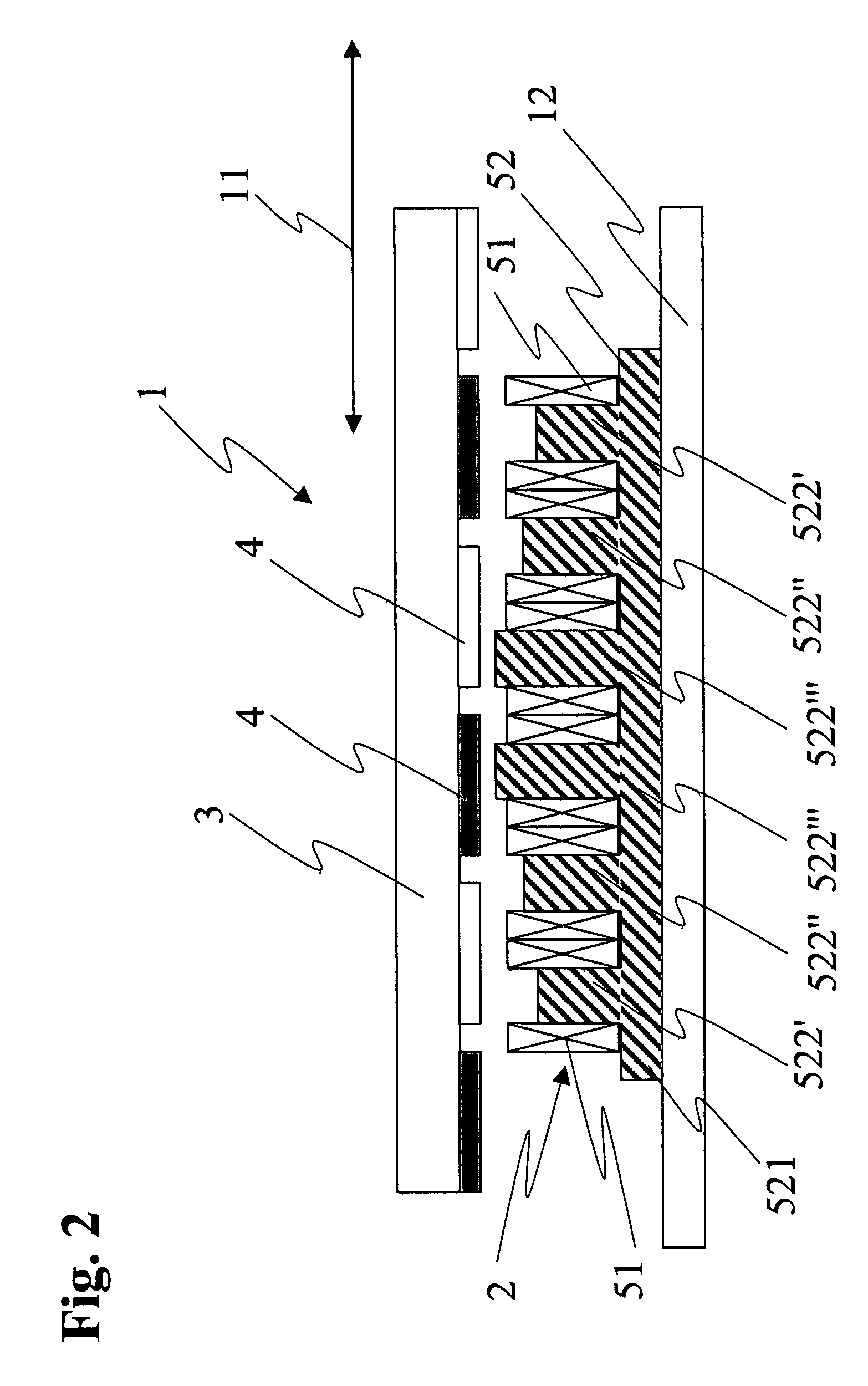
[0031]The ideal height of the individual iron poles 522 for given overall dimensions of a linear motor can be determined by corresponding FEM simulations, in which the heights of the iron poles are varied until the amplitude of the detent force modulation is minimal. An iron set with a depth of 20 mm, a length in the running direction of 52 mm, a height of the iron core of 3.2 mm and a maximum height of 10.5 mm has six iron poles. All the iron poles have a length of 4 mm in the running direction and are separated by 4 mm-wide grooves. The height of the six coils which are turned over the iron poles is respectively 7.1 mm. The optimized heights of the individual iron poles were calculated by 3D FEM simulation for a stator which is dimensioned in such a way, in which the amplitude of the transversal component of the detent force is minimal in the running direction, with the two innermost iron poles with a fixed height over the iron core of 7.3 mm not having been varied. An optimum was...


PUM


Abstract

In a linear motor (1), the detent force is reduced by the height of the iron poles (522) being selected differently in the two outer regions of the coil set, preferably by a gradual reduction of the height of the iron poles (522) towards the ends of the stator (2). In combination with a slight inclination of the magnets, the detent forces are further minimized, with negligible losses of the propulsive force.The exact dimensioning of the iron poles (522) is dependent inter alia on the dimensioning of the coils (51) and other characteristics of the linear motor (1) as a whole, and can be found and optimized by simulations. Here, an optimum is sought between as great a reduction as possible of the detent force amplitude and as high a propulsive force as possible. A linear motor (1) according to the invention has substantially the same manufacturing costs as a conventional linear motor without measures against the detent forces, because no costly active devices are necessary and the production of the stator does not become more complicated. As no additional space is necessary for active or passive devices for detent force reduction, such a linear motor is of more compact construction and therefore has a higher power density.

Description

[0001]This application claims priority to Swiss application No. 01779 / 06 filed Nov. 9, 2006.TECHNICAL FIELD[0002]The present invention relates to an iron core linear motor with a stator and a runner displaceably arranged along a running axis of the stator, in accordance with the introductory clause of the independent patent claim.PRIOR ART[0003]In modern automation technology, brushless linear motors are no longer unthinkable as actuators. They reach high speeds, and nevertheless reach a high precision into the nanometer range. For many applications of such linear motors, for example in linear axes or cross-tables, in addition as small a volume as possible of the linear motors is desired with, at the same time, as high an output as possible.[0004]Linear motors are electric motors and consist of an immovable stator and a runner which is displaceable with respect to the stator along a running axis, said runner basically corresponding to the movable rotor in a rotating electric motor. ...

Claims


Application Information

Patent Timeline
Patent Type & Authority Patents(United States)
IPC IPC(8): H02K41/02H02K33/18H02K41/025H02K41/03
CPCH02K41/031H02K29/03H02K2201/03
Inventor JENNY, ALOIS
Owner JENNY ALOIS
Why Eureka
Try Eureka