Electronic scanning radar apparatus

a radar and electronic technology, applied in the field of electronic scanning radar apparatus, can solve the problems of difficult detection at such an accuracy, complex whole machine, high cost, etc., and achieve the effect of careful search

Active Publication Date: 2010-03-30
DENSO CORP
View PDF8 Cites 19 Cited by
  • Summary
  • Abstract
  • Description
  • Claims
  • Application Information

AI Technical Summary

Benefits of technology

[0030]According to this aspect of the invention, two or more short time data, which is comprised of M numbers of data, number of which is small in a time direction, are cut out from the received data which are comprised of N numbers of data, and the inverse matrix of the correlation matrix is estimated from the thus cut short time data so as to compute the CAPON phase information, thereby computing the distance of a target and an azimuth thereof from the CAPON phase information. Then, targets B1 and B2 can be separated from each other in the distance component, making the best use of the characteristic of the CAPON, as shown in FIG. 7 and FIG. 8. In other words, it is possible to extract the phase information with high accuracy.
[0032]According to this aspect of the invention, the inverse in matrix (Rff−1) of the time series correlation matrix is computed and estimated by the successive processing of estimating of the inverse matrix with the RLS, so that the number of computation of the inverse matrix for which large amount of operations are necessary can be extremely decreased, thereby saving the operation cost and enlarging the data size.
[0034]According to this aspect of the invention, the cut data varying means can vary the data quantity to be cut out, so that the resolution can be properly switched between the distance resolution and the azimuth resolution, depending on the search object of the target to foe obtained, thereby carefully searching.
[0036]According to this aspect of the invention, the distance / azimuth switching means can switch the resolution, laying stress on the distance or the azimuth according to a position of a target to be searched, and careful search is possible, thereby.

Problems solved by technology

But, in such a structure that the AD converter is prepared for each antenna element, the whole machine is made complex and expensive.
Secondly, an accuracy of the phase information is uniquely determined by broadening of a main lobe of FFT, that is, by sampling frequency and number of sampling, and it is difficult to detect at such an accuracy depending on a distance to a target that distance accuracy has a priority in a short distance, and azimuth accuracy has a priority in a long distance.

Method used


Image

  • Electronic scanning radar apparatus
  • Electronic scanning radar apparatus
  • Electronic scanning radar apparatus

Examples


Embodiment Construction

[0037]Embodiments of the invention will now be explained, referring to appended drawings.

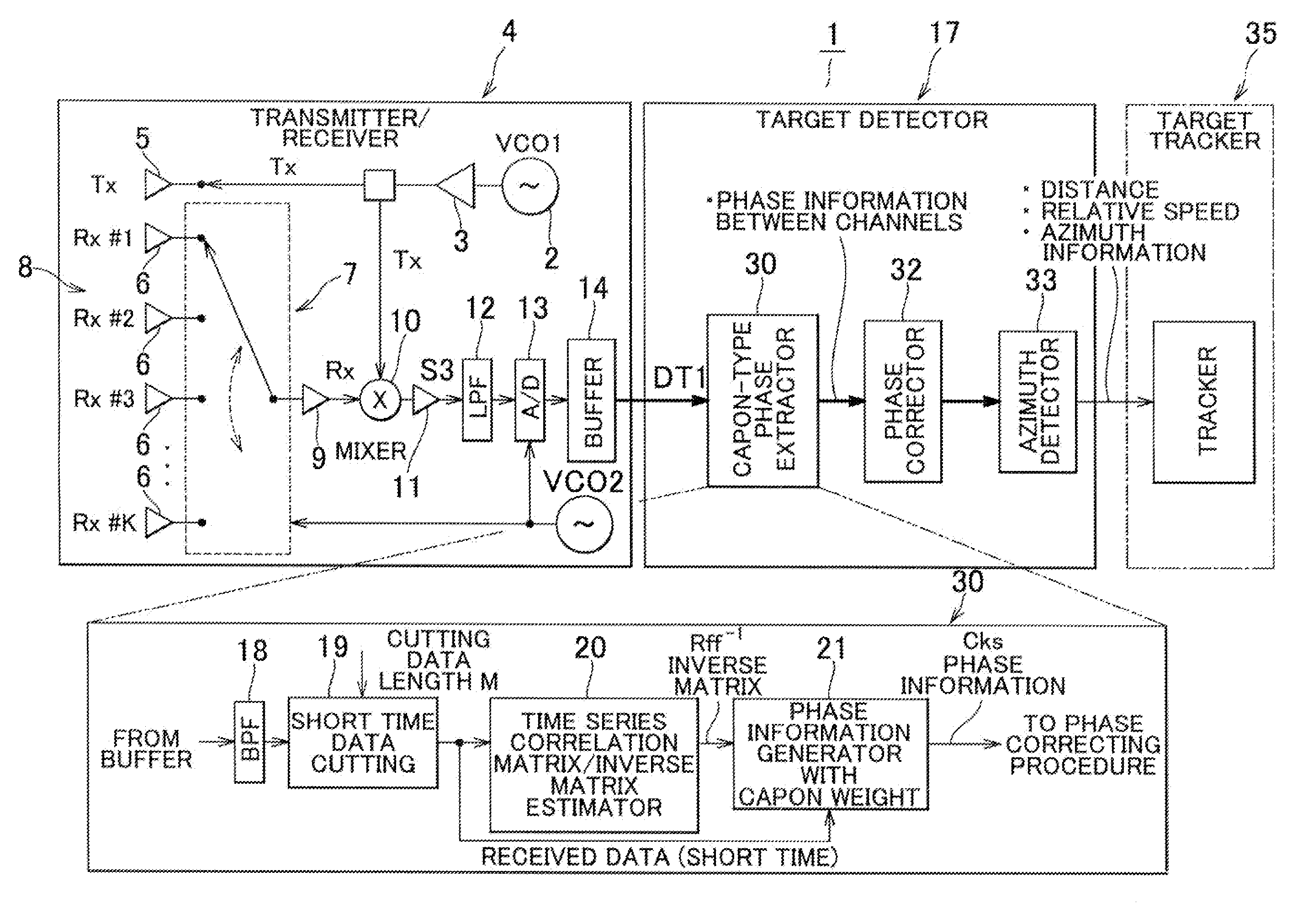
[0038]FIG. 3 is a block diagram showing an embodiment of an electronic scanning radar apparatus according to the invention, FIG. 4 is a typical view showing a processing of cutting short time data, FIG. 5 is a typical view showing a processing of computing CAPON weight matrix, FIG. 6 is a block diagram showing the other embodiment of the electronic scanning radar apparatus according to the invention, FIG. 7 is a view for comparing distance resolution in producing and computing of phase information between a case (a) with CAPON and a case (b) with FFT, and FIG. 8 is a partially enlarged view showing an import ant part of FIG. 7.

[0039]FIG. 3 is a block diagram showing an electronic scanning radar apparatus 1 which is an embodiment of the invention. This radar apparatus 1 is a FM-CW radar apparatus wherein a transmitted signal Tx which is obtained by executing frequency modulation (FM; on continuou...


PUM


Abstract

An electronic scanning radar apparatus has a cutting portion for cutting receiving data which is comprised of N numbers of data for each channel into two more short time data having M (<N) numbers of data in a time direction for each channel, an inverse matrix estimator for computing and estimating an inverse matrix of the time series correlation matrix from the short time data, and a phase information producing portion for computing CAPON phase information out of the estimated inverse matrix of the time series correlation matrix in order to detect a distance, an azimuth and a relative speed of a target on the basis of a computed CAPON phase information.

Description

[0001]This application claims benefit of priority to Japanese Patent Application No. 2006-50782 filed on Feb. 27, 2006.BACKGROUND OF THE INVENTION[0002]This invention relates to an electronic scanning radar apparatus, and especially to a FM-CW type of electronic scanning radar apparatus for use on vehicle.[0003]FIG. 1 is a time-chart showing transmitted signals and received signals and a principle of mixing in a FM-CW radar and FIG. 2 is a block diagram showing a conventional FM-CW type of electronic scanning radar apparatus.[0004]On-vehicle radars for measuring distance, speed and azimuth with respect to a preceding target which exists in a forward direction have been developed in order to control an automotive vehicle crash prevention and tracking traveling.[0005]A FM-CW radar system is used far measuring distance and relative speed with respect to a preceding target since this system has a simple structure of a signal processing circuit. As shown in FIG. 1, a signal S1 which freq...

Claims


Application Information

Patent Timeline
Patent Type & Authority Patents(United States)
IPC IPC(8): G01S13/34G01S13/58G01S13/00G01S13/931
CPCG01S13/345G01S13/426G01S13/584G01S13/931
Inventor SUZUKI, KOICHIROYAMANO, CHIHARUTAKANO, GAKUNATSUME, KAZUMA
Owner DENSO CORP
Why Eureka
Try Eureka