Marine radar systems and methods

a radar system and radar technology, applied in the field of marine radar systems and methods, can solve the problems of unwanted artifacts and cluttered radar display, and achieve the effects of improving range resolution, reducing noise, and improving sensitivity

Active Publication Date: 2010-03-30
HONEYWELL INT INC
View PDF31 Cites 30 Cited by
  • Summary
  • Abstract
  • Description
  • Claims
  • Application Information

AI Technical Summary

Benefits of technology

[0009]The present invention provides improved sensitivity on a pulse-by-pulse basis using NLFM pulse compression. The pulse-to-pulse stepped frequency processing of pulse compressed sub-pulses—with stepped center frequencies—provides higher effective system bandwidth which translates to improved range resolution. This combination allows for a transmitter and receiver with low transmission power and limited bandwidth to maintain a high SNR and achieve much higher effective bandwidth than the hardware is able to instantaneously support. The required sensitivity varies on the environment the radar will be operating in and the rada

Problems solved by technology

A Self-calibration process is periodically performed to reduce amplitude and phase deformations and to regulate the range-ti

Method used


Image

  • Marine radar systems and methods
  • Marine radar systems and methods
  • Marine radar systems and methods

Examples


Embodiment Construction

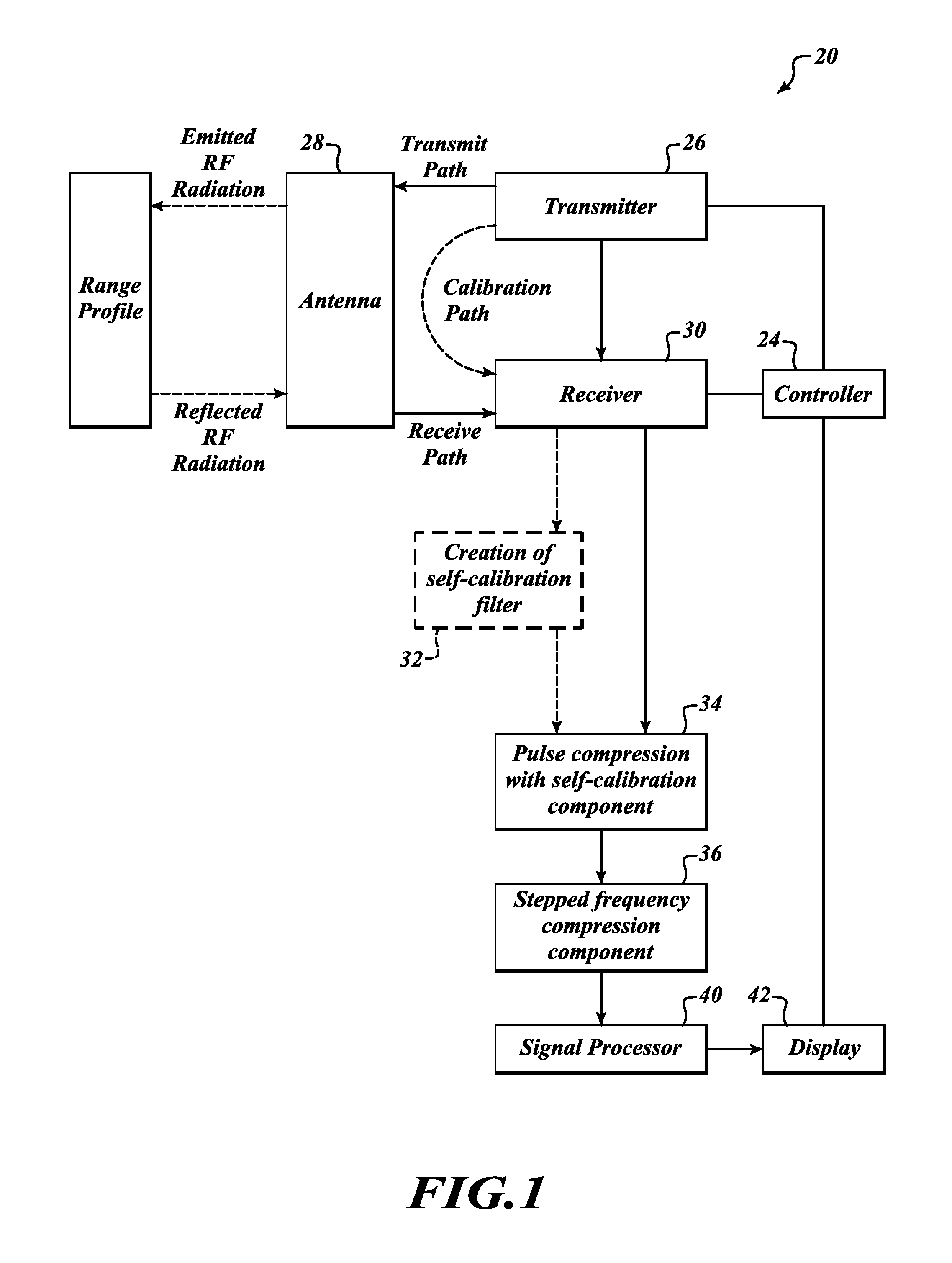
[0015]FIG. 1 is a block diagram of an exemplary embodiment of a marine radar system 20. The system 20 includes a controller 24, a transmitter 26, an antenna 28, a receiver 30, signal calibration and compression components (32, 34, 36), a signal processor 40, and a display device 42.

[0016]The transmitter 26 generates and emits a radar waveform signal as directed by controller settings. The antenna 28 directs the signal generated by the transmitter 26. The antenna 28 is swept such that the system is able to detect objects in an area of interest about the installation. A radar return is reflected energy from an object upon which the emitted radar pulse is incident on. The received radar returns are communicated to the receiver 30.

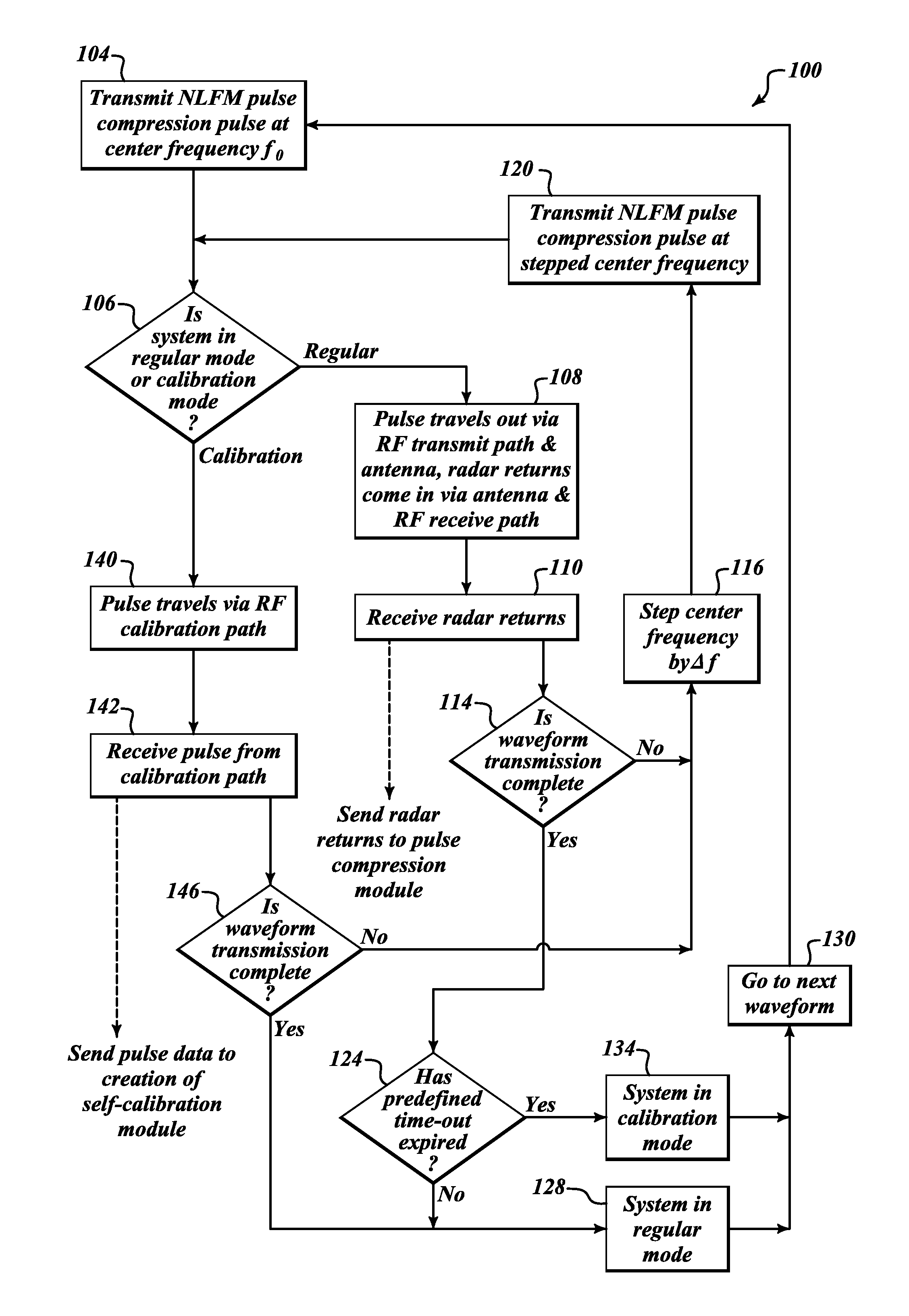
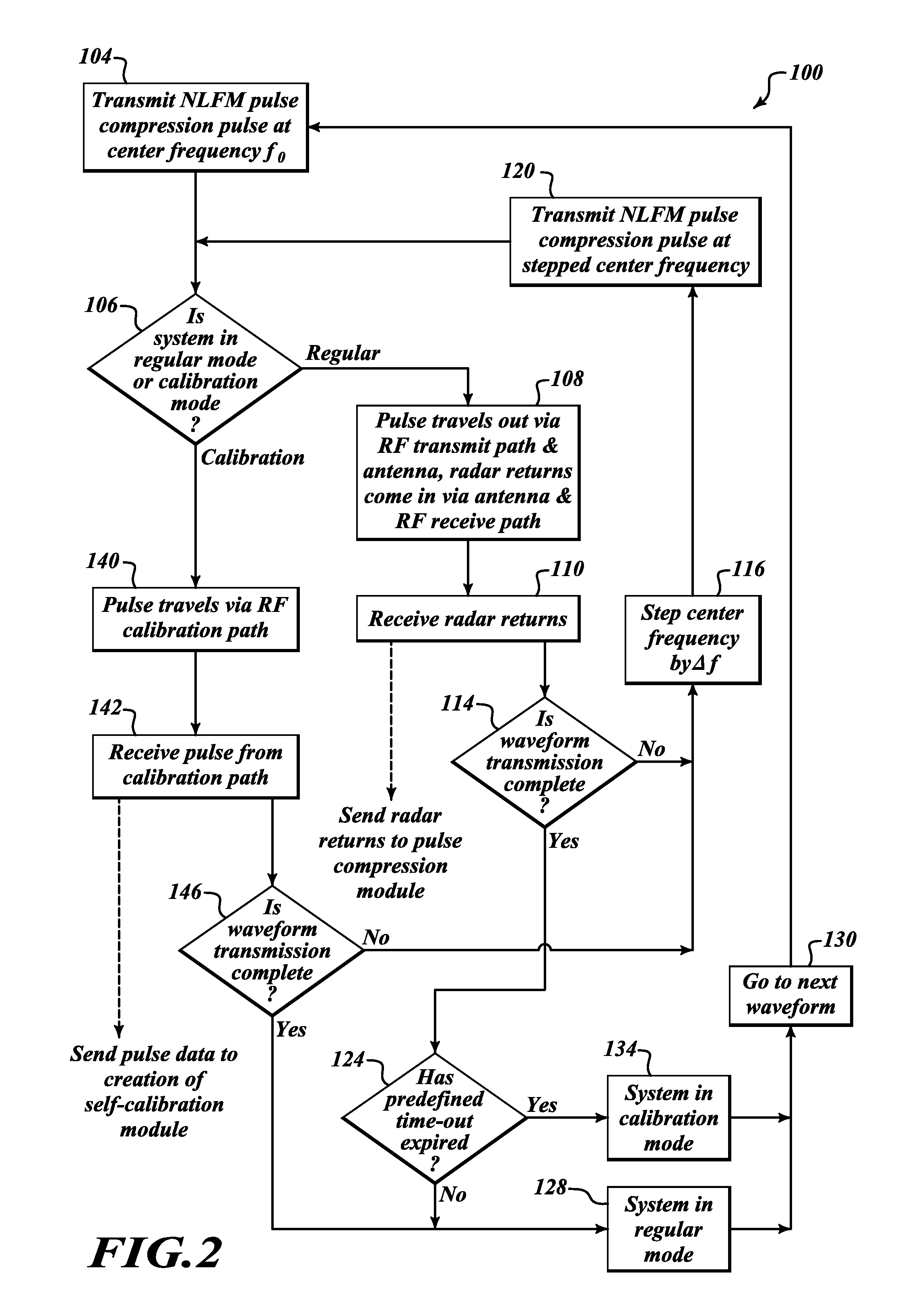
[0017]The marine radar transmitter 26 generates a non-linear frequency modulation (NLFM) stepped frequency sub-pulse and transmits it via the antenna 28. Reflections are detected by the receiver 30, calibrated and pulse compressed in the module 34, and stored ...


PUM


Abstract

Marine radar systems and methods for producing low power, high resolution range profile estimates. Non-linear Frequency Modulation (NLFM) pulse compression pulses are frequency stepped to form a low power, wide-bandwidth waveform. Periodically, calibration filters are determined and applied to return signals for correcting non-ideal effects in the radar transmitter and receiver.

Description

BACKGROUND OF THE INVENTION[0001]Marine radars are transitioning from high power magnetron transmitters to low power solid-state transmitters as they offer lower maintenance, more consistent performance, and the ability to be more discrete when transmitting. The challenge with low-power transmitters becomes keeping range resolution high while retaining a high signal-to-noise ratio (SNR). Two such methods are pulse compression and stepped frequency, both of which require advanced waveforms and associated methods to transmit and receive them while minimizing the non-ideal effects of the hardware to keep processing artifacts from cluttering the subsequent range profile estimates. A range profile represents the volume of space illuminated by the RF energy directed out of the radar antenna for a given pointing direction. Marine radars that use non-linear FM pulse compression waveforms (or any type of pulse compression waveform) are faced with the challenge of keeping range sidelobes low ...

Claims


Application Information

Patent Timeline
IPC IPC(8): G01S7/40G01S13/26
CPCG01S13/30G01S7/4008G01S13/286G01S7/4052G01S7/4017G01S7/4021G01S2007/4069G01S7/4069
Inventor CHRISTIANSON, PAULLOGAN, GLORIAKILTY, BRENNAN
Owner HONEYWELL INT INC
Why Eureka
Try Eureka