

Segmentation of regions in measurements of a body based on a deformable model
a segmentation and model technology, applied in the field of spatial segmentation measured values of a body, can solve the problems of inability to provide a sharp contrast edge in the measured value, the segmentation process to determine the significant regions in the measured value set is tedious and time-consuming, and the segmentation process cannot handle large data sets. to achieve the effect of reducing the measurement of curvatur
- Summary
- Abstract
- Description
- Claims
- Application Information
AI Technical Summary
Benefits of technology
Problems solved by technology
Method used
Image

Examples
Embodiment Construction
[0002]This invention was made with Government support under Grant No. DAMD17-99-1-9034 awarded by the Department of Defense and Grant No. RG01-0071 awarded by the Whitaker Foundation. The Government has certain rights in the invention.
BACKGROUND OF THE INVENTION
[0003]1. Field of the Invention
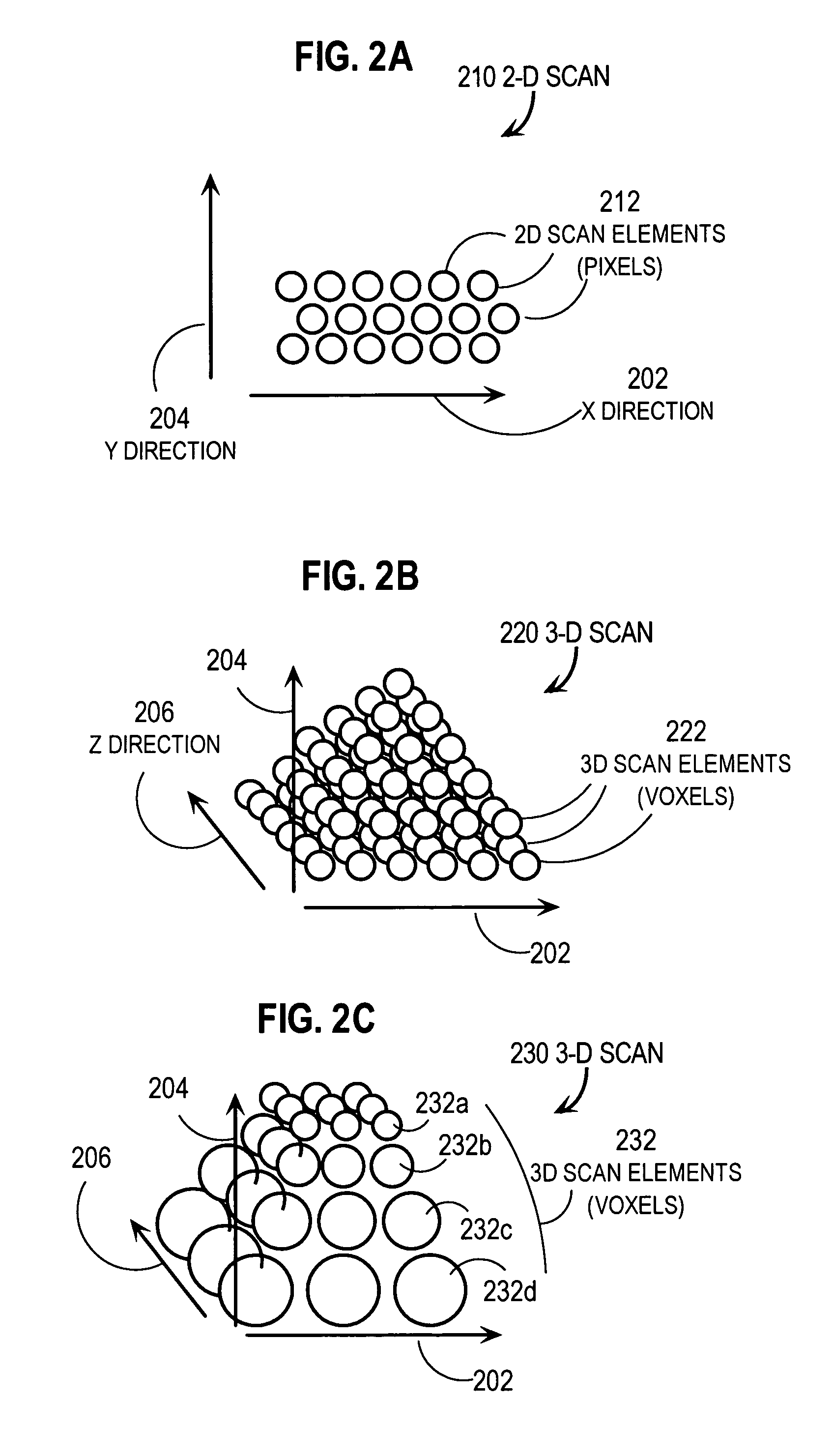
[0004]The present invention relates to spatially segmenting measured values of a body, such as a patient, to interpret structural or functional components of the body; and, in particular to automatically segmenting three dimensional scan data such as Computer Tomography X-Ray (CT) scan data and echogram data.
[0005]2. Description of the Related Art
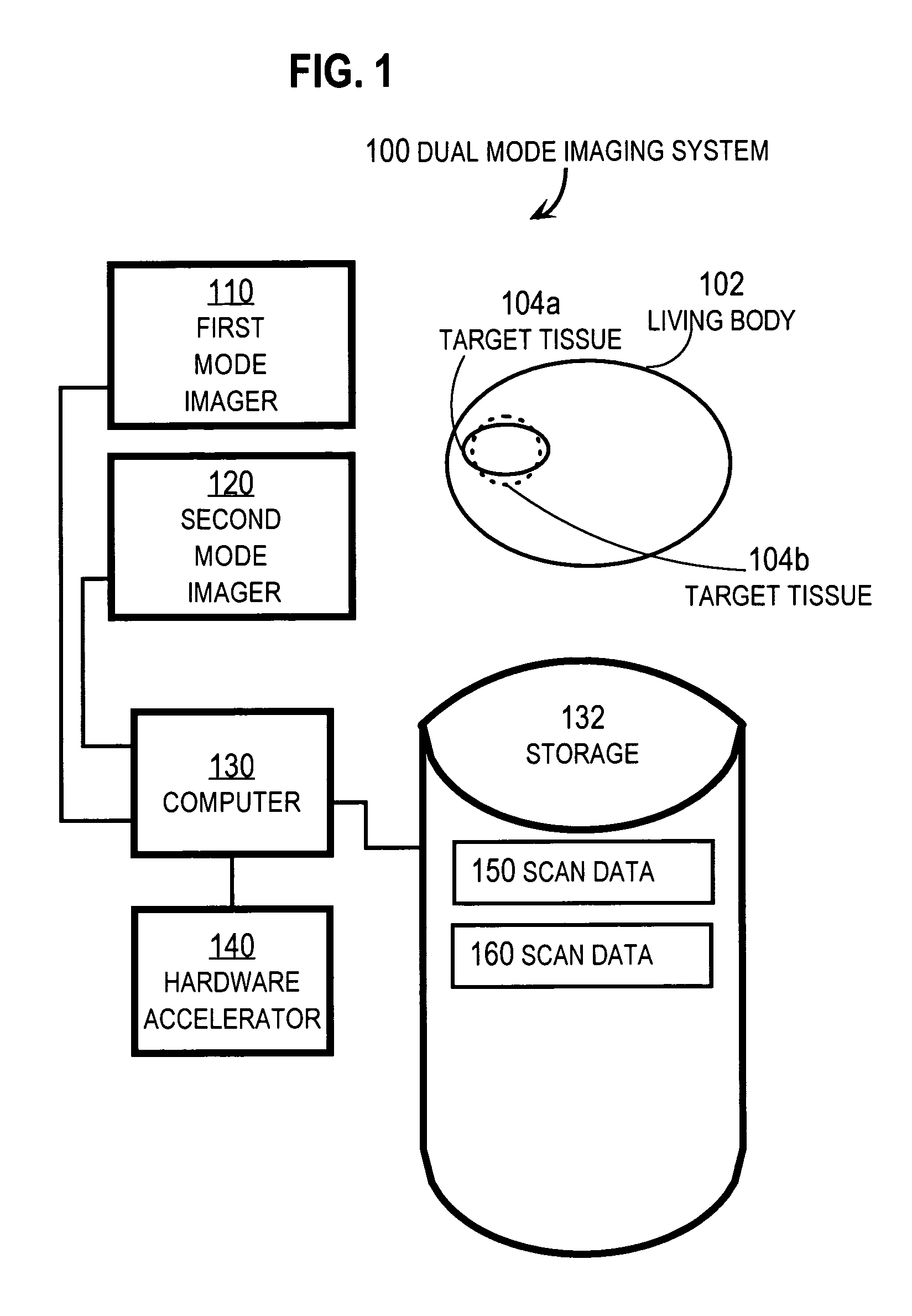
[0006]Different sensing systems are widely known and used for non-invasively probing the interior structure of bodies. For example, X-rays and X-ray-based computer-aided tomography (CT), nuclear magnetic resonance (NMR) and NMR-based magnetic resonance imagery (MRI), acoustic waves and acoustics-based ultrasound imagery (USI), positron emissions and pos...
PUM
 Abstract
Description
Claims
Application Information