System, method, and apparatus for structural lug formed from a combination of metal and composite laminate materials

a technology of composite laminate materials and systems, applied in the field of structural anchors, can solve the problems of composite structure ultimate failure mode, heavy weight of metallic lugs, fatigue cracking, etc., and achieve the effects of reducing the need for additional tooling

Active Publication Date: 2010-04-06
LOCKHEED MARTIN CORP
View PDF31 Cites 27 Cited by
  • Summary
  • Abstract
  • Description
  • Claims
  • Application Information

AI Technical Summary

Benefits of technology

[0008]In one embodiment, the metallic base may incorporate an integrally machined chamfer to minimize peel stresses in the composite layers. The top metallic layers are fitted over and bonded to the composite plies and act as the outermost layers of the lug. In one embodiment, the lateral ends of the lug where the top layers come into contact with the machined base may be joined to the base with friction stir welding (FSW), mechanical fasteners (e.g., bolts), etc., to form the completed, sandwich-like structure. Another feature of the invention is that the metallic base and metallic outer plies act as a pre-formed mold for the composite plies and, thus, eliminate the need for additional tooling when curing the structure.
[0009]The invention is lighter in weight than a comparable all-metal lug, but has a safer, more damage-tolerant failure mode than a purely composite design. The reduction in weight helps reduce the overall weight of the underlying structure to which the lug is secured. Also, having a more damage tolerant structure and a more predictable mode of failure in lugs is important for many applications including aircraft. This solution also provides an efficient design that is easily attached to other objects.

Problems solved by technology

Unfortunately, lugs formed from both types of materials have some disadvantages.
Metallic lugs are heavy and are subject to fatigue cracking.
However, the primary concern with non-metallic lugs is with the ultimate failure mode of a composite structure.
For example, composites typically have a brittle failure mode.
This means that if a composite lug suffers a large enough crack it will fail catastrophically very quickly.
In contrast, a metallic lug has a more ductile failure that may be prolonged before complete failure.

Method used


Image

  • System, method, and apparatus for structural lug formed from a combination of metal and composite laminate materials
  • System, method, and apparatus for structural lug formed from a combination of metal and composite laminate materials
  • System, method, and apparatus for structural lug formed from a combination of metal and composite laminate materials

Examples


Embodiment Construction

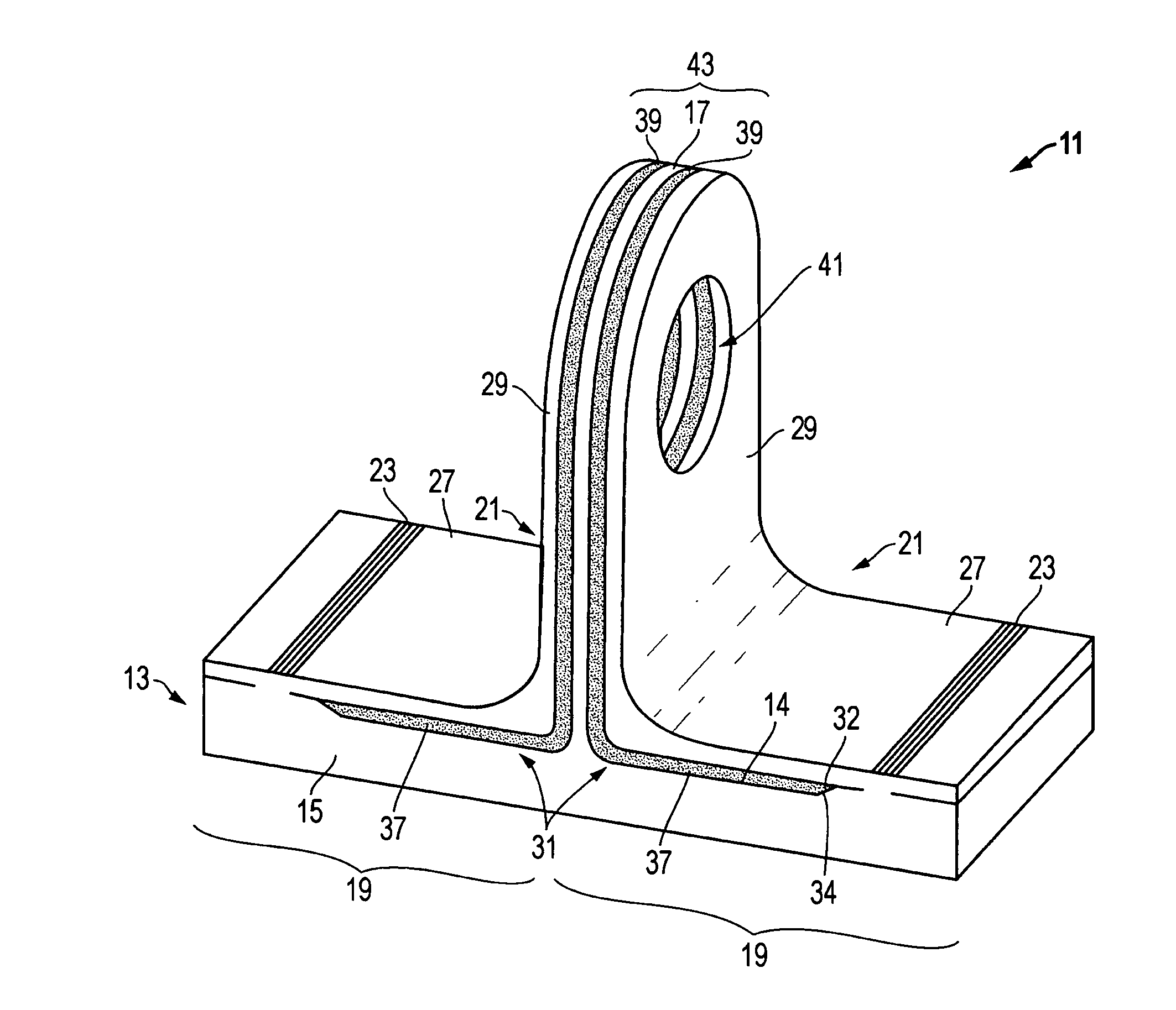
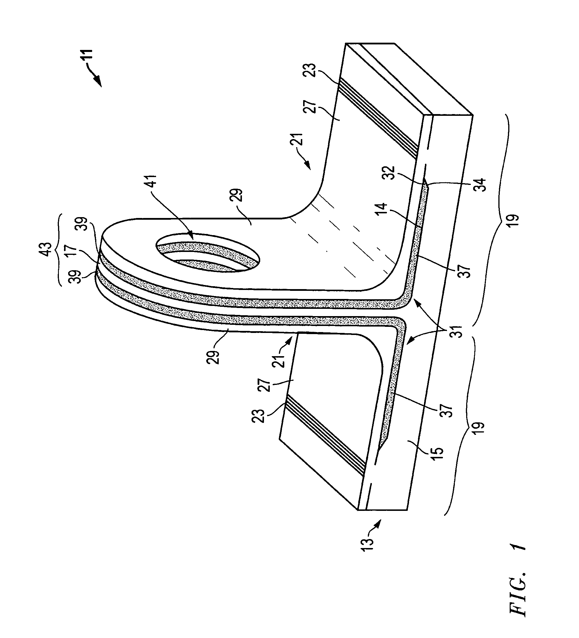
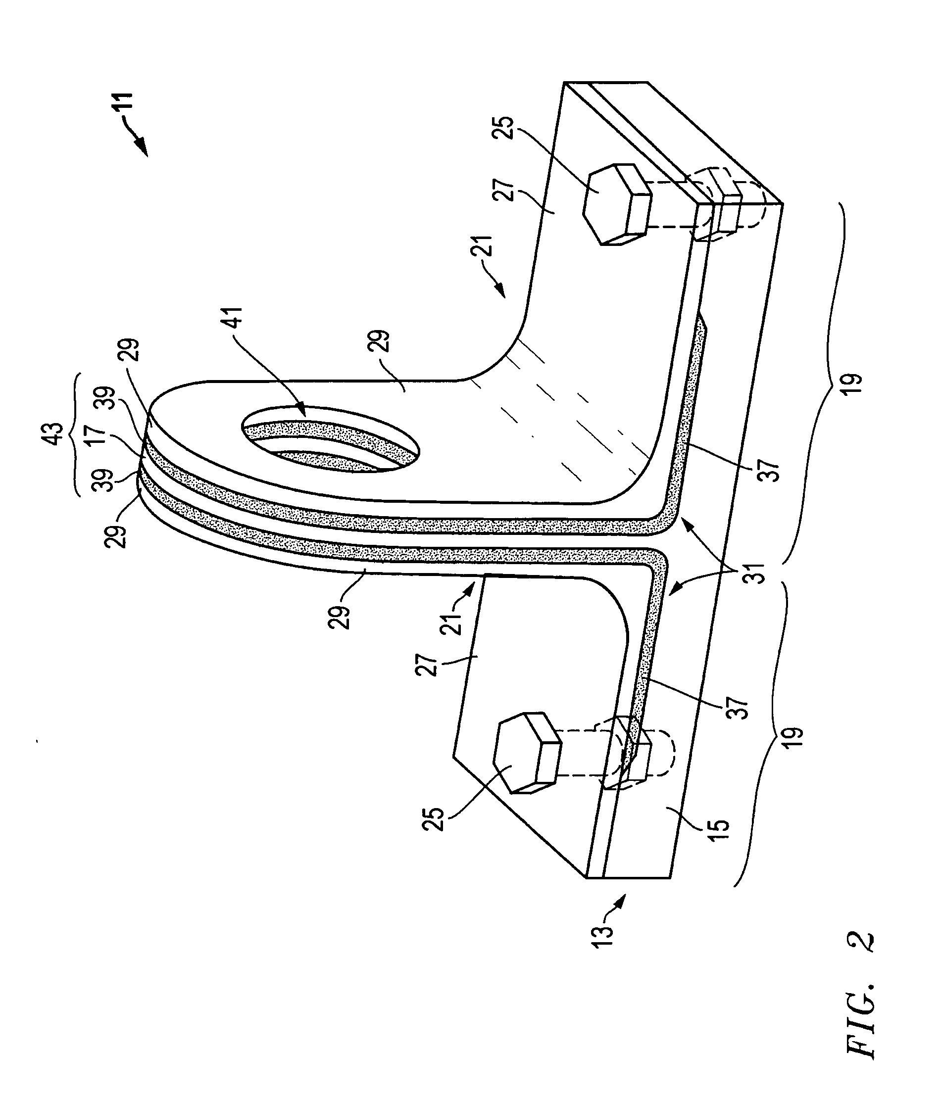
[0017]Referring to FIGS. 1-5, embodiments of a system, method, and apparatus for a structural lug are shown. As shown in FIGS. 1-4, one embodiment of the structural lug 11 comprises a foundation 13 formed from a metallic material (e.g., metal, metal alloy, etc.). The foundation 13 has a base 15 and a tongue 17 extending from the base 15. In the illustrated embodiment, the tongue 17 extends perpendicularly from a central portion of the base 15 to bifurcate the foundation 13 into two lateral portions 19.

[0018]The lug 11 also comprises outer plies 21 that are formed from a metallic material and secured to the foundation 13. The outer plies 21 may be friction stir welded 23 (FIG. 1) to the foundation 13, secured to the foundation 13 with mechanical fasteners 25 (FIG. 2), or joined thereto via other means. The outer plies 21 may comprise a pair of L-shaped outer plies having base portions 27 and tongue portions 29.

[0019]A third major component of lug 11 is intermediate plies 31. Intermed...


PUM

PropertyMeasurementUnit
non-metallicaaaaaaaaaa
sizeaaaaaaaaaa
brittle failureaaaaaaaaaa

Abstract

A structural lug comprising a metallic base, composite middle layers, and outer layers of metallic material is disclosed. The metallic base of the structure is machined to accommodate the composite plies, which are located on each lateral side of the base and bonded to the base with adhesive. The composite material may comprise an adhesive-based resin with embedded fibers. The metallic base may be formed to minimize peel stresses in the composite layers. The top metallic layers are fitted over and bonded to the composite plies and act as the outermost layers of the lug. The lateral ends of the lug where the top layers come into contact with the machined base may be joined together with friction stir welding or mechanical fasteners to form the completed structure.

Description

BACKGROUND OF THE INVENTION[0001]1. Technical Field[0002]The present invention relates in general to structural anchors and, in particular, to an improved system, method, and apparatus for a structural lug formed from multiple dissimilar materials such as metals and composite laminates.[0003]2. Description of the Related Art[0004]In the prior art, structural anchoring connectors known as “lugs” are very common and important structures in the aerospace and other industries. Lugs are used as a means of connecting two or more structures and act as primary load paths for the underlying structures. Lugs formed from metallic materials such as alloys are the most common and are widely used for many types of applications. Lugs formed from entirely from non-metallic materials (e.g., composite materials) have become increasingly common as well for other types of applications.[0005]Unfortunately, lugs formed from both types of materials have some disadvantages. Metallic lugs are heavy and are ...

Claims


Application Information

Patent Timeline
Patent Type & Authority Patents(United States)
IPC IPC(8): E04C1/00
CPCB29C70/68B29C66/43441B29C66/721B29C66/742Y10T428/24182B29L2031/3076Y10T156/1052Y10T156/10B29K2105/06
Inventor WALKER, JARED T.BARNES, JOHN E.
Owner LOCKHEED MARTIN CORP
Why Eureka
Try Eureka