Vehicle wheel

a technology for vehicles and wheels, applied in the field of vehicles, can solve the problems of increased manufacturing cost, unsuitable mass production of vehicles, and inability to meet the needs of vehicles, and achieve the effect of reducing manufacturing manpower and cost, and improving the mass productivity of vehicles

Active Publication Date: 2010-04-06
HONDA MOTOR CO LTD
View PDF18 Cites 38 Cited by
  • Summary
  • Abstract
  • Description
  • Claims
  • Application Information

AI Technical Summary

Benefits of technology

[0010]The vehicle wheel according to the present invention is different from a vehicle wheel described in Japanese Patent Laid-open Publication No. 2004-90669 in that the vehicle wheel according to the present invention can be manufactured by only fitting in the additional air chamber member, which has the additional air chamber in advance, between the first vertical wall surface and the second vertical wall surface formed on the well portion, on the contrary, in the vehicle wheel described in the Japanese Patent Laid-open Publication No. 2004-90669, a plurality of separators, cap member, and etc. are sequentially assembled with the wheel, then, the additional air chambers are formed by accurately jointing these considering airtightness.
[0016]In the vehicle wheel, since contacts of tools such as a lever and the tire with the additional air chamber member are reduced, a tire mounting performance is improved.
[0019]In the vehicle wheel, since the well portion fixing the additional air chamber member can be shifted to further inner side in the radial direction, a circumferential length of the well portion can be shortened. Therefore, weight saving of the vehicle wheel is further improved.
[0023]In the vehicle wheel, since a member other than the protruding portion is unnecessary for forming the communication hole, the structure of the vehicle wheel can be simplified and the weight of the vehicle wheel can be further reduced.
[0025]In the vehicle wheel, when the centrifugal force generated by the rotation of the vehicle wheel works on the additional air chamber member, the edge portion extending to the circumferential direction from the main body is secured by the first vertical wall surface and the second vertical wall surface. Therefore, a periphery end portion of the additional air chamber member is prevented from lifting up from the outer circumferential surface of the well portion.
[0026]According to a vehicle wheel of the present invention, the vehicle wheel can be manufactured by only fitting in an additional air chamber member, which has an additional air chamber in advance, between the first vertical wall surface and the second vertical wall surface. Accordingly, mass productivity of the vehicle wheel can be improved, as well as the manufacturing manpower and cost can be reduced in comparison with the conventional vehicle wheel.

Problems solved by technology

However, the vehicle wheel described above has not a practical structure.
Therefore, a mass production of the vehicle wheel has been unsuitable considering securing of the airtightness, a manufacturing manpower, and an increase in the manufacturing cost.

Method used


Image

  • Vehicle wheel
  • Vehicle wheel
  • Vehicle wheel

Examples


Embodiment Construction

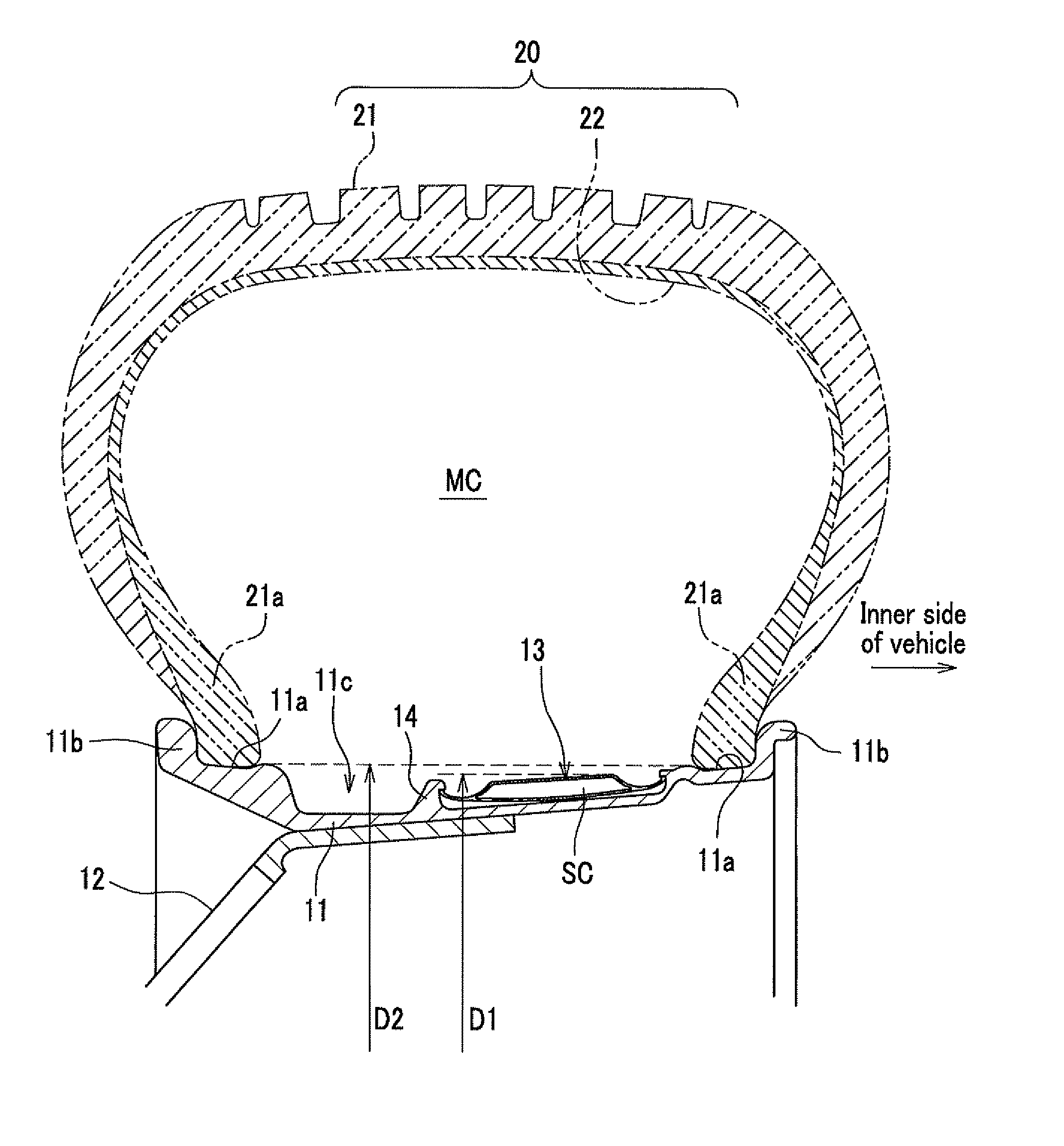
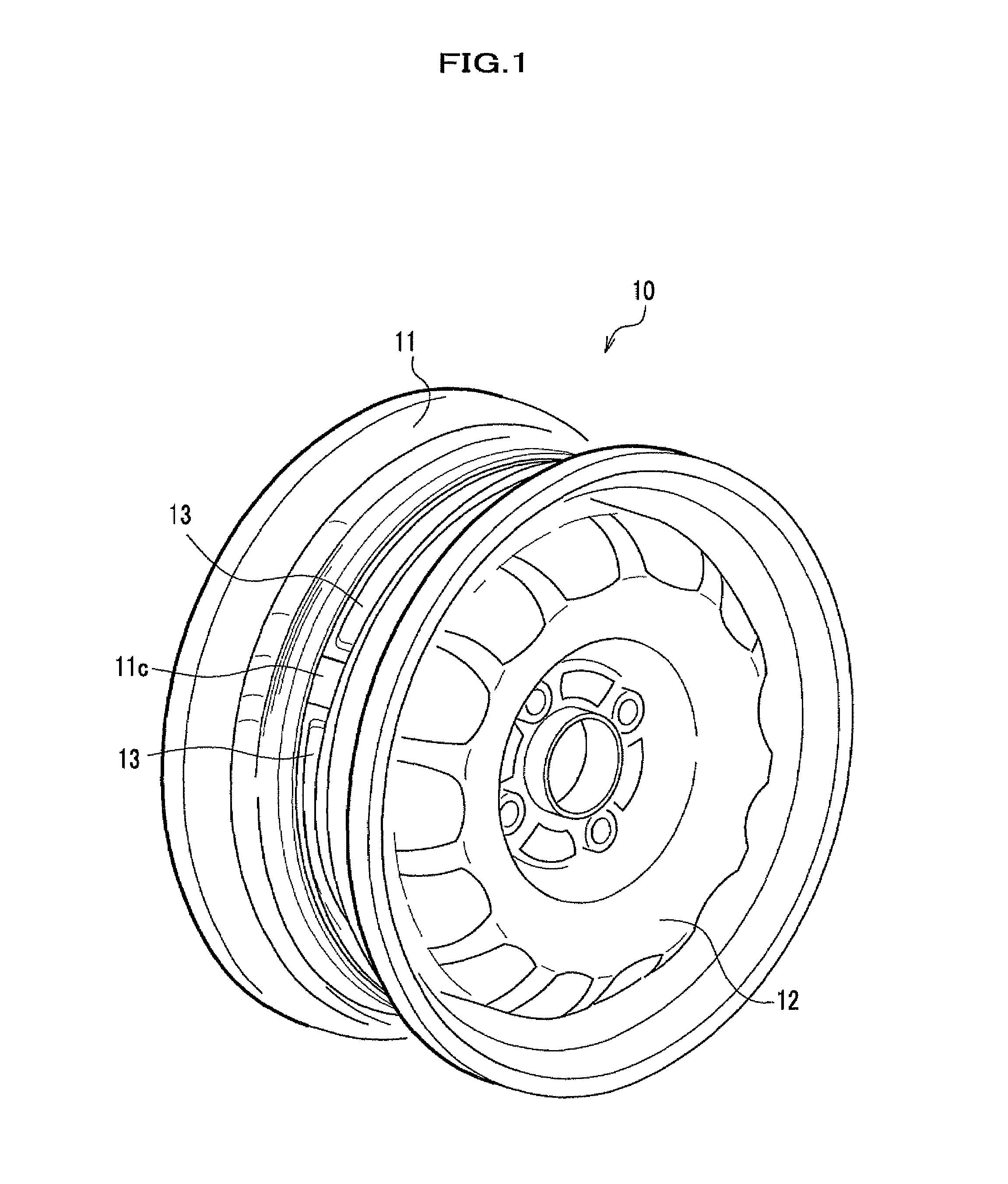
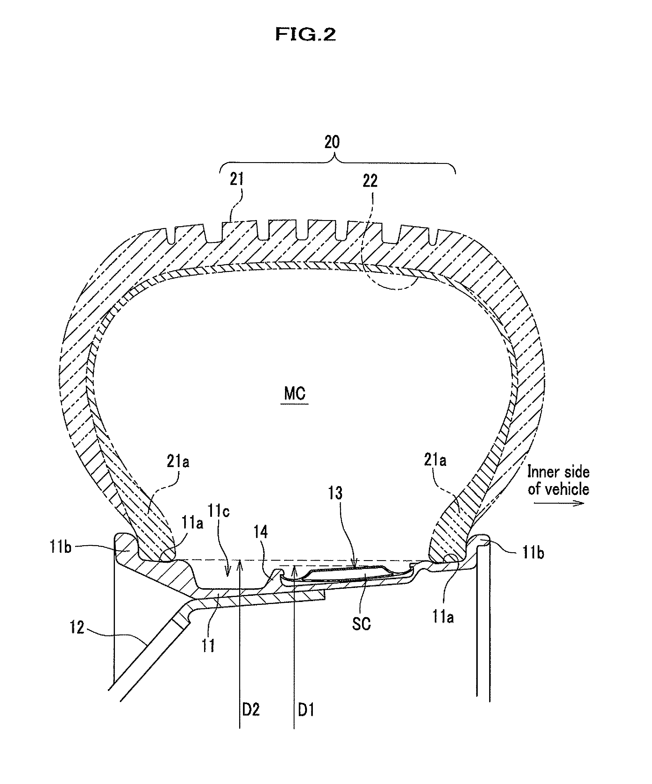
[0042]Hereinafter, a vehicle wheel according to the embodiment of the present invention will be explained in details by referring to drawings as appropriate. FIG. 1 is a perspective view of a vehicle wheel according to an embodiment of the present invention. FIG. 2 is a main part front cross sectional view of a wheel mounting a tire on a vehicle wheel shown in FIG. 1. FIG. 3A is a main part front cross sectional view in which a well portion on which an additional air chamber member is fixed is partially enlarged. FIG. 3B is a perspective view of a recess formed in a vertical wall of the well portion.

[0043]A vehicle wheel according to the present invention is characterized in that an additional air chamber member (Helmholtz resonator) is fitted in and fixed on a well portion side. Here, a whole constitution of the vehicle wheel will be explained first, and then, a constitution of the additional air chamber member will be explained.

[0044]As shown in FIG. 1, a vehicle wheel 10 accordin...


PUM


Abstract

A vehicle wheel in which an additional air chamber member in a tire air chamber is fixed on an outer circumferential surface of a well portion, includes: a first vertical wall surface rising outward in a radial direction from the outer circumferential surface of the well portion and extending in a circumferential direction of the outer circumferential surface; and a second vertical wall surface formed in the well portion facing the first vertical wall surface. The additional air chamber member has an additional air chamber and a communication hole formed therein. The communication hole provides communication between the additional air chamber and the tire air chamber. The additional air chamber member is fitted between the first and second vertical wall surfaces. Side end portions of the additional air chamber member in a width direction of the vehicle wheel are secured between the first and second vertical wall surfaces.

Description

CROSS REFERENCE TO RELATED APPLICATIONS[0001]This application claims the foreign priority benefit under Title 35, United States Code, §119(a)-(d) of Japanese Patent Application No. 2007-125139, filed on May 10, 2007, the contents of which are hereby incorporated by reference.BACKGROUND OF THE INVENTION[0002]1. Field of the Invention[0003]The present invention relates to a vehicle wheel which reduces a noise emission accompanying an air column resonance (cavernous resonance) inside an air chamber of a tire.[0004]2. Description of Related Art[0005]In general, it is known that an air column resonance generated in an air chamber of a tire (hereinafter, referred to as tire air chamber) causes a road noise of a vehicle. The air column resonance is a phenomenon which generates a resonant sound in such a manner that an air in the tire air chamber is vibrated due to random vibrations transmitted from a road surface to the tire, and as a result, a resonant phenomenon occurs at around an air c...

Claims


Application Information

Patent Timeline
Patent Type & Authority Patents(United States)
IPC IPC(8): B60B21/02B60C19/00
CPCB60B3/044B60B21/023B60C19/002B60B21/12B60C19/00B60B21/026
Inventor KAMIYAMA, YOUICHIKASHIWAI, MIKIOTAKAGI, HISAMITSU
Owner HONDA MOTOR CO LTD
Why Eureka
Try Eureka