Golf ball

a golf ball and mid layer technology, applied in golf balls, solid balls, sports equipment, etc., can solve the problems of insufficient resilience performance of the mid layer, poor flight performance of golf balls, and excessive spin upon a driver shot, so as to improve the flight distance, improve the impact feel, and improve the impact resistance.

Inactive Publication Date: 2010-04-06
SUMITOMO RUBBER IND LTD
View PDF13 Cites 16 Cited by
  • Summary
  • Abstract
  • Description
  • Claims
  • Application Information

AI Technical Summary

Benefits of technology

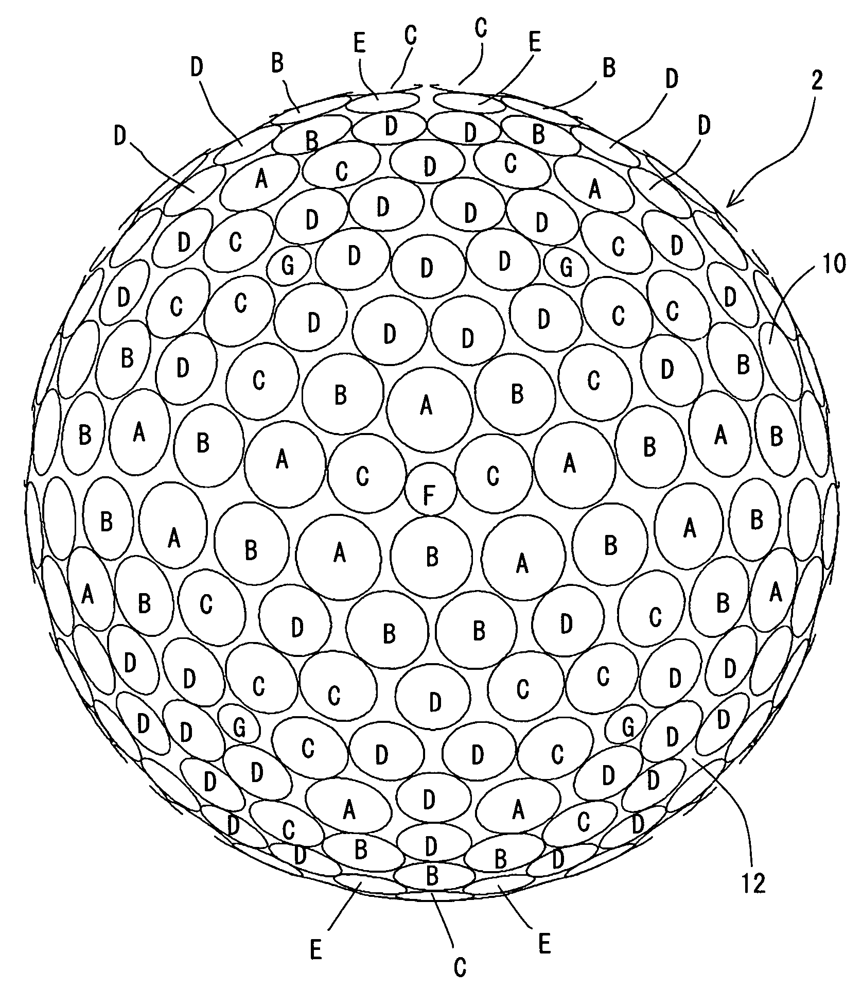
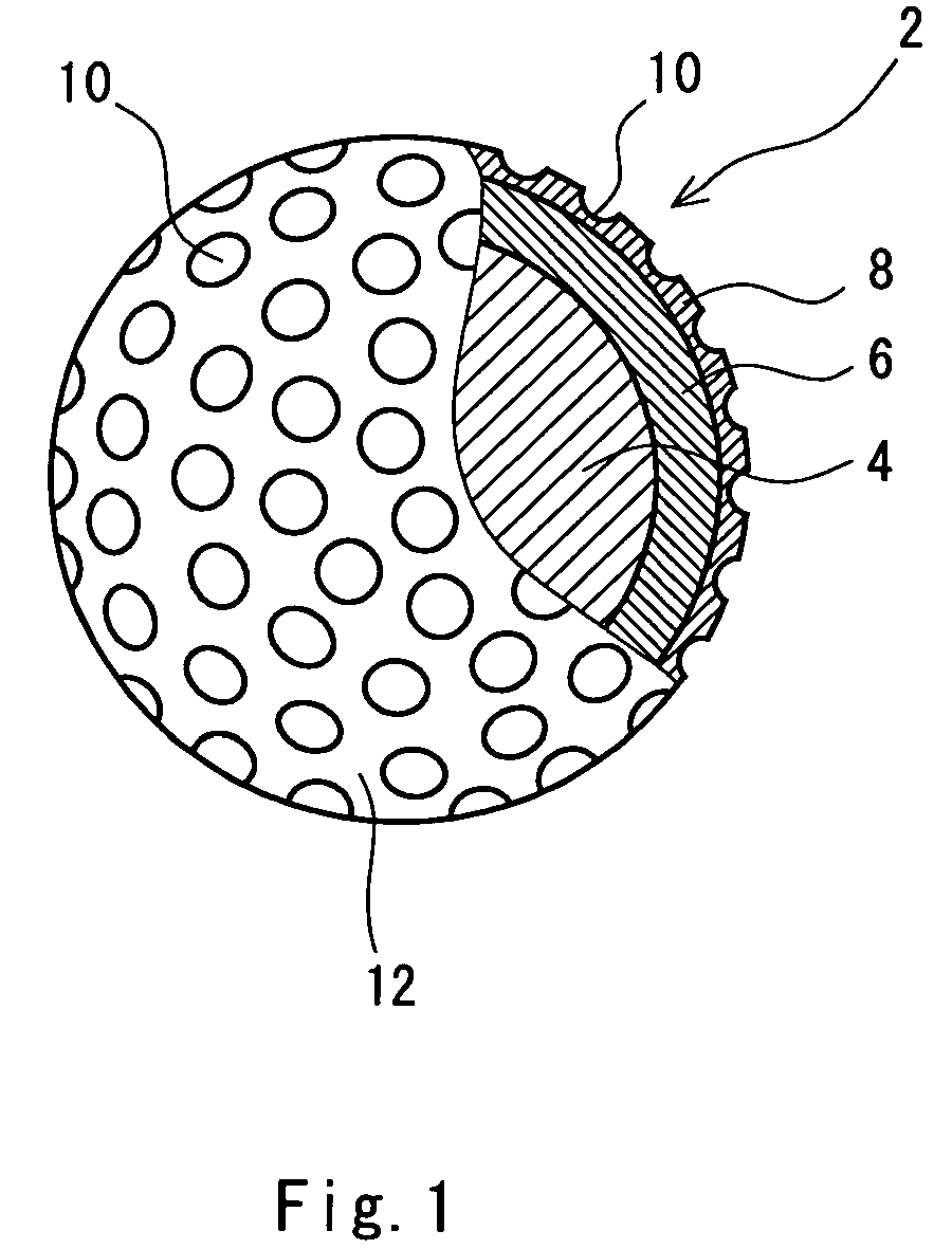
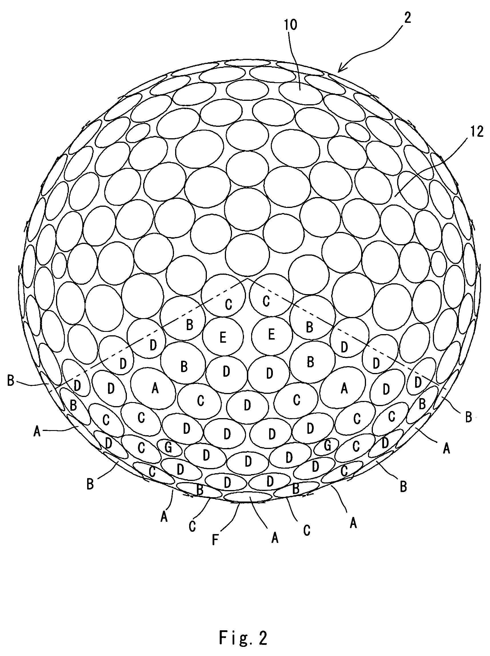
[0012]A soft thermoplastic elastomer containing a styrene block and a hard ethylene-(meth)acrylic acid copolymer based ionomer resin are used in combination in the mid layer of this golf ball, and the thickness of the mid layer is small. This mid layer is responsible for a favorable feel at impact and an excellent resilience performance. This mid layer is also responsible for optimization of a deformation behavior upon impact with a driver at a relatively slow head speed. Optimization of the deformation behavior results in suppression of the spin, thereby elevating the flight distance. According to this golf ball, it is speculated that Dx / Dn being equal to or greater than 1.30 is responsible for reduction of the drag. According to this golf ball, it is speculated that the standard deviation η being equal to or less than 0.52 is responsible for enhancement of the lift force. This golf ball achieves a great dimple effect irrespective of suppressed spin.

Problems solved by technology

According to golf balls disclosed in U.S. Pat. No. 6,299,551 and U.S. Pat. No. 6,213,896, a resilience performance of the mid layer is insufficient.
These golf balls are inferior in a flight performance.
According to a golf ball disclosed in U.S. Pat. No. 6,576,707, spin upon a driver shot is apt to be excessive resulting from the mid layer having high hardness.
Excessive spin leads to reduction of the flight distance.
The mid layer having high hardness also adversely affects a feel at impact.

Method used


Image

  • Golf ball
  • Golf ball
  • Golf ball

Examples


example 1

[0105]A rubber composition was obtained by kneading 100 parts by weight of polybutadiene (trade name “BR-11”, available from JSR Corporation), 24 parts by weight of zinc diacrylate, 5 parts of zinc oxide, an adequate amount of barium sulfate, 0.5 part by weight of bis(pentabromophenyl)disulfide and 0.6 part by weight of dicumyl peroxide. This rubber composition was placed into a mold having upper and lower mold half each having a spherical cavity, and heated at a temperature of 170° C. for 30 minutes to obtain a core having a diameter of 37.5 mm. A type c resin composition listed in Table 2 below was covered around this core by a compression molding method to form a mid layer having the thickness Tm of 1.0 mm. This spherical body comprising the core and the mid layer was placed into a mold having numerous protrusions on the inside face, followed by injection of a type X resin composition listed in Table 3 below around the spherical body according to an injection molding method to fo...


PUM

PropertyMeasurementUnit
thicknessaaaaaaaaaa
diametersaaaaaaaaaa
diameteraaaaaaaaaa

Abstract

A golf ball 2 has a core, a mid layer and a cover. This mid layer comprises 10 parts by weight or greater and 70 parts by weight or less of a thermoplastic elastomer containing a styrene block having a material hardness of less than 10, and 30 parts by weight or greater and 90 parts by weight or less of an ethylene-(meth)acrylic acid copolymer based ionomer resin having a material hardness of 50 or greater and 70 or less. Hardness of this mid layer is less than 40, and the thickness is equal to or less than 1.2 mm. This golf ball 2 has seven kinds of dimples (A to G), each having a different diameter. When all the dimples are arranged in decreasing order of the diameter Di, ratio (Dx / Dn) of the mean diameter Dx of the dimples ranking in the top 10% to the mean diameter Dn of the dimples ranking in the bottom 10% is equal to or greater than 1.30. Standard deviation η of diameters of all the dimples is equal to or less than 0.52.

Description

[0001]This application claims priority on Patent Application No. 2003-386546 filed in Japan on Nov. 17, 2003.BACKGROUND OF THE INVENTION[0002]1. Field of the Invention[0003]The present invention relates to golf balls. More particularly, the present invention relates to solid golf balls having a core, a mid layer and a cover.[0004]2. Description of the Related Art[0005]Golf balls have numerous dimples on the surface thereof. A role of the dimples involves causing turbulent flow separation through disrupting the air flow around the golf ball during the flight. This roll is referred to as a “dimple effect”. By causing the turbulent flow separation, a separating point of air from the golf ball shifts backwards leading to the reduction of drag. The turbulent flow separation promotes the differentia between the separating points at the upper and lower sides of the golf ball, which results from the backspin, thereby enhancing the lift force that acts upon the golf ball. Excellent dimples d...

Claims


Application Information

Patent Timeline
Patent Type & Authority Patents(United States)
IPC IPC(8): A63B37/12A63B37/00A63B37/04C08F265/04C08F279/02C08F285/00C08L23/08C08L53/00
CPCA63B37/0004A63B37/0075C08F265/04C08F279/02C08F285/00C08L53/00A63B37/12A63B37/0045A63B37/0043A63B37/0039A63B37/0033A63B37/0031A63B37/0021A63B37/002A63B37/0006A63B37/0012A63B37/0017A63B37/0018C08F236/06C08F220/14C08L23/0876C08L2666/06
Inventor OHAMA, KEIJISAJIMA, TAKAHIROENDO, SEIICHIRO
Owner SUMITOMO RUBBER IND LTD
Why Eureka
Try Eureka