
Semipermeable membrane system for magnetic particle fractions

a magnetic particle and membrane technology, applied in the direction of magnetic separation, separation process, filtration separation, etc., can solve the problems of limiting the use possibilities of a technical endosmosis to certain material groups, requiring a cyclic discontinuous operation, and reaching the binding capacity limit relatively quickly

Inactive Publication Date: 2010-04-06
KERNFORSCHUNGSZENTRUM KARLSRUHE GMBH
View PDF11 Cites 2 Cited by
  • Summary
  • Abstract
  • Description
  • Claims
  • Application Information

AI Technical Summary

Benefits of technology

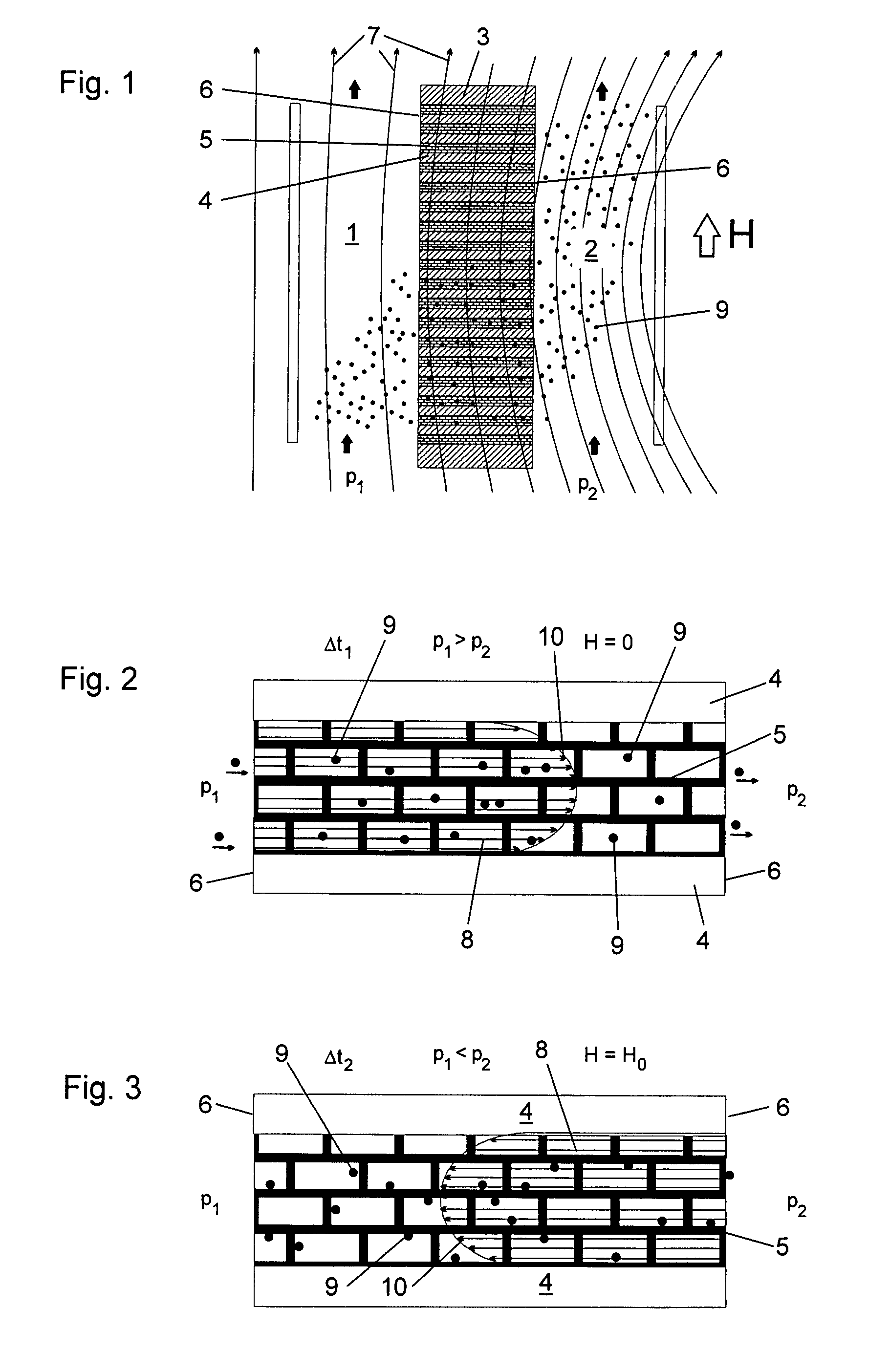
[0013]In a semi-permeable membrane system for separating magnetic particle fractions from a mixture contained in a first fluid, comprising a membrane with opposite membrane surfaces between which passages extend and which separates the first fluid from a second fluid each of which is in contact with one of the membrane surfaces, means are provided for generating a reversible pressure differential between the two fluids across the membrane for alternately causing a fluid flow through the membrane in opposite directions and means for alternately generating and eliminating a magnetic field in the membrane so that, during the fluid flow in one direction, the magnetic field is switched on to hold the magnetic particles in place in the membrane and, during fluid flow in the opposite flow direction, the magnetic field is switched off to permit the magnetic particles to be moved through the membrane in the other direction.
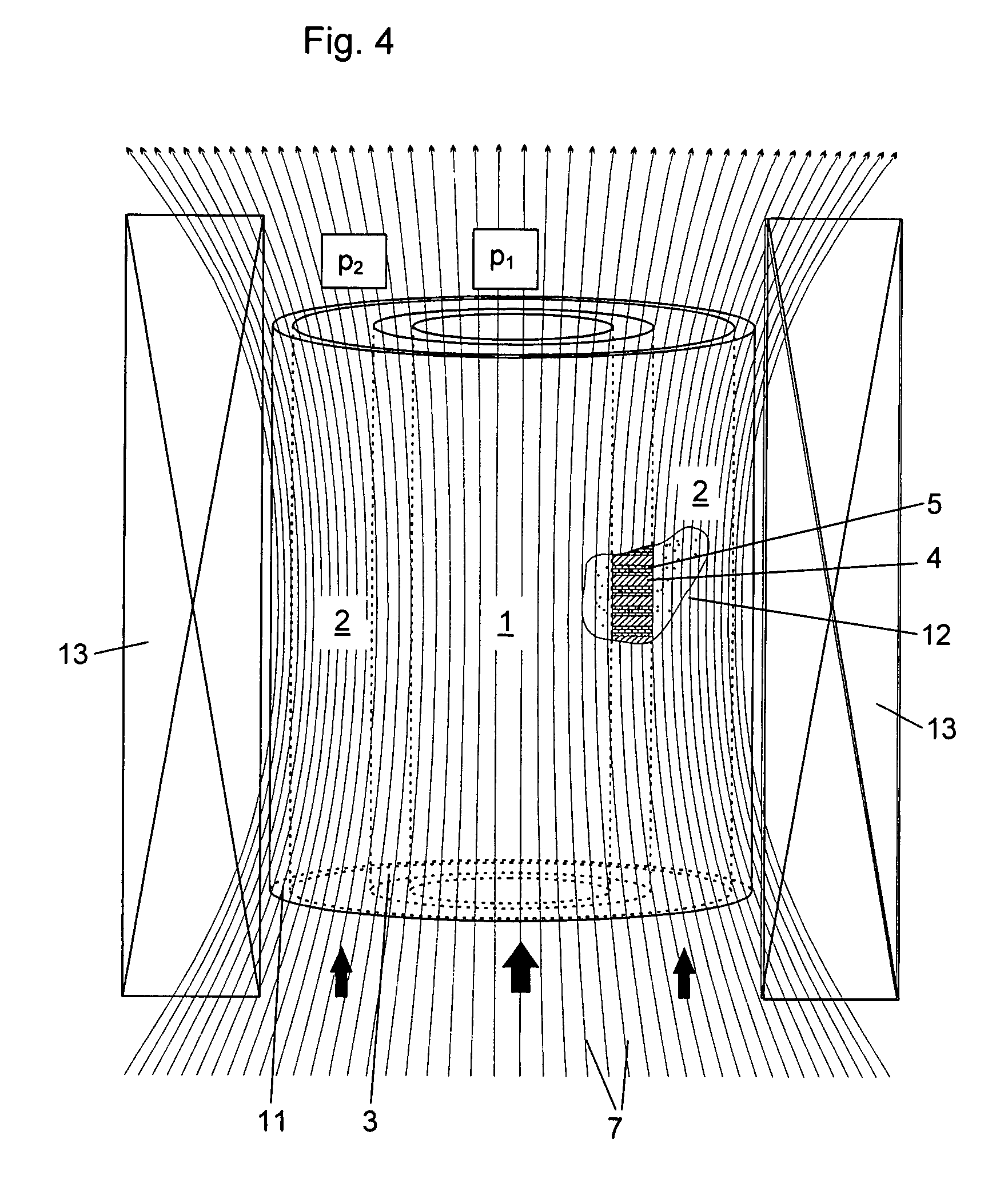
[0017]This effect can be increased if the membrane, and particularly the channel walls, consist fully or partially of a magnetic material. The activated magnetic field focuses itself, as a result, in the area of the membrane in the manner as described below. Furthermore, the magnetically excited wall acts like the poles of a magnet on the magnetic particle fractions and significantly increases the forces effective on the particles and, consequently, the adhesion of the particles to the wall. The membrane comprises preferably several flat layers of a solid magnetic material through which a fluid can flow and which are stacked on top of one another in alternating order and between the two membrane surfaces.
[0026]An interesting combination of the use of selective carrier particles and the above-mentioned membrane resides in the utilization of the above-mentioned magnetic particle fractions as micro-sorbants. Herein, the magnetic particle fractions are functionalized as carrier particles in the size range of a few micrometers or less in such a way that they bind certain substances selectively. The removal of the magnetic micro-sorbants from the surrounding solution, that is, from the remaining non-magnetic components of the fluid occurs by means of the above-mentioned separation procedures, whereby the micro-sorbants concentration is increased at one side of the membrane. Advantageously, in this way, also certain non-magnetic fluid components can be separated together with the magnetic particle fractions from other non-absorbing non-magnetic components.

Problems solved by technology

The selection features of the materials to be separated are based therefore on the electric charges (positive or negative) or hydrophilic or hydrophobic properties, which limits the use possibilities of a technical endosmosis to certain material groups.
However, with the sorption principle the binding capacity limit is reached relatively rapidly and the flow must then be stopped to avoid a breakthrough.
However, in contrast to the continuous method of regular semi-permeable membranes, membranes operating on a sorption basis require a cyclic discontinuous operation.

Method used


Image

  • Semipermeable membrane system for magnetic particle fractions
  • Semipermeable membrane system for magnetic particle fractions
  • Semipermeable membrane system for magnetic particle fractions

Examples


Embodiment Construction

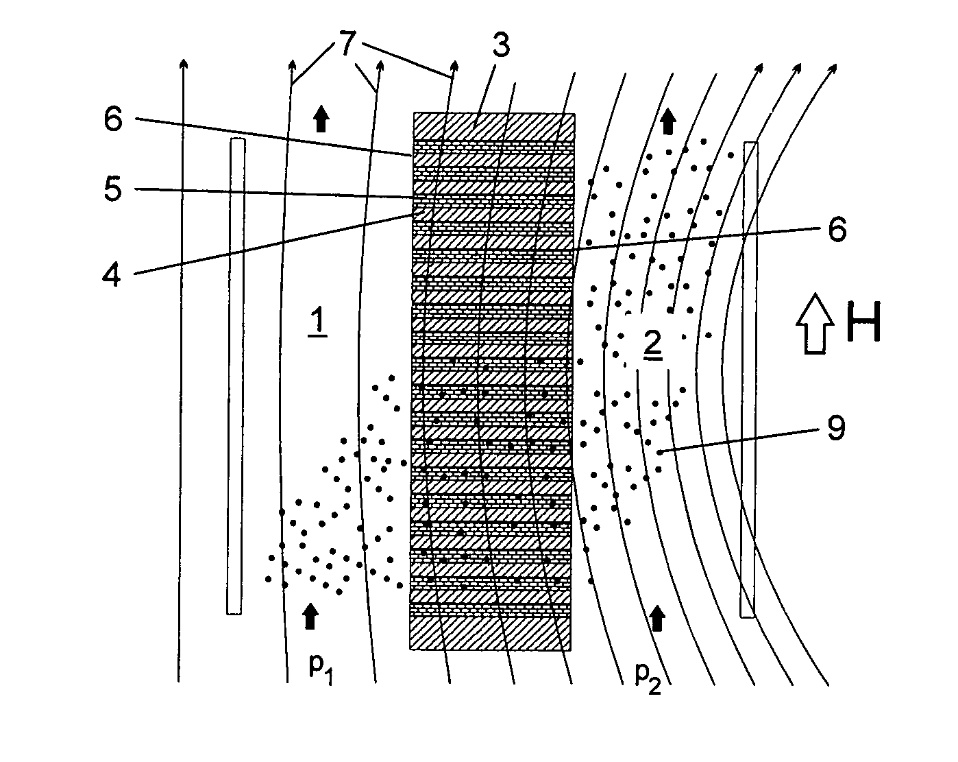
[0039]FIG. 1 shows schematically in a cross-sectional view the essential components of a first embodiment with a plate-shaped membrane 3 forming a separation wall between two fluids 1 and 2 which are moved parallel to the membrane and have pressures P1 and, respectively, P2. The membrane comprises a sandwich structure consisting of alternate layers of a ferromagnetic solid material 4 and layers of a ferromagnetic wire web 5. The layers mentioned extend orthogonally with respect to the two membrane surfaces 6. The open spaces in the wire mesh provide the micro-fluidic channels forming the fluid passages between the two membrane surfaces. The lateral dimension of the layers, particularly of the ferromagnetic web 5 between the membrane surfaces 6 herein is a multiple of its thickness or, respectively, height. The whole magnet membrane additionally stands under the influence of a switchable magnetic field indicated in FIG. 1 by the magnetic field lines 7 (magnetic field strength H). Not...


PUM

PropertyMeasurementUnit
magnetic particle fractionaaaaaaaaaa
pressureaaaaaaaaaa
magnetic fieldaaaaaaaaaa

Abstract

In a semi-permeable membrane system for transferring magnetic particle fractions contained in a first fluid to a second fluid, comprising a membrane through which passages extend and which separates the first fluid from the second fluid being a pressure generation arrangement is provided for generating a reversible pressure differential between the two fluids across the membrane for alternately causing fluid movement in the membrane in opposite directions and a magnetic field generator is provided for alternately generating a magnetic field in the membrane wherein, during the fluid movement in one direction, the magnetic field is switched on to hold the magnetic particles in place in the membrane and, during fluid flow in the opposite flow direction, the magnetic field is switched off to permit the magnetic particles to be moved through the membrane in the other direction.

Description

[0001]This is a Continuation-In-Part Application of pending International Application PCT / EP2005 / 013426 filed Dec. 14, 2005 and claiming the priority of German Application 10 2004 062 535.2 filed Dec. 24, 2004.BACKGROUND OF THE INVENTION[0002]The invention resides in a semi-permeable membrane for magnetic particle fractions in a fluid having two membrane surface forming a separation structure between two fluid fractions and at least one channel bridging the membrane.[0003]A membrane of this type is in contrast to vibrating membranes—a separation membrane—which forms a separation layer between two fluid volumes. A semi-permeable (osmotic) membrane is only permeable by certain materials or components of a fluid whereas, it forms an impermeable barrier for other materials. This selective material exchange, also called osmosis, can occur in both directions (diosmosis) or, as in the present case, in one direction (endosmosis).[0004]Semi-permeable membranes are, for example, necessary com...

Claims


Application Information

Patent Timeline
Patent Type & Authority Patents(United States)
IPC IPC(8): B01D35/06
CPCB01D61/002B01D71/022B01D69/06B01D69/02B01D61/0024B01D61/0023
Inventor FRANZREB, MATTHIASROGGE, TILMANN
Owner KERNFORSCHUNGSZENTRUM KARLSRUHE GMBH
Learn More