Exposure apparatus, operation decision method, substrate processing system, maintenance management method, and device manufacturing method

a technology of operation decision and substrate, applied in the direction of photosensitive materials, instruments, printers, etc., can solve the problems of difficult to achieve an operating rate of 95% or more, and extremely difficult to achieve an operating rate of 95% in the present situation, so as to improve the productivity of highly integrated microdevices. , the effect of improving the productivity of highly integrated microdevices

Active Publication Date: 2010-04-06
NIKON CORP
View PDF40 Cites 12 Cited by
  • Summary
  • Abstract
  • Description
  • Claims
  • Application Information

AI Technical Summary

Benefits of technology

[0010]The present invention has been made in consideration of the situation described above, and has as its first object to provide an exposure apparatus that can improve an operating rate without lowering apparatus performance in the case the exposure apparatus is inline connected to a substrate processing apparatus.
[0011]The second object of the present invention is to provide an operation decision method that can improve an operating rate without lowering apparatus performance in the case an exposure apparatus is inline connected to a substrate processing apparatus.
[0012]The third object of the present invention is to provide a substrate processing system that can improve an operating rate while maintaining performance of the system.

Problems solved by technology

However, it is not easy to achieve an operating rate of 95% or more even in the case of the exposure apparatus alone.
Accordingly, in the system in which the exposure apparatus and the C / D are inline connected (hereinafter, referred to as an ‘inline lithography system’), it can be said that it is extremely difficult to achieve an operating rate of 95% in the present situation.

Method used


Image

  • Exposure apparatus, operation decision method, substrate processing system, maintenance management method, and device manufacturing method
  • Exposure apparatus, operation decision method, substrate processing system, maintenance management method, and device manufacturing method
  • Exposure apparatus, operation decision method, substrate processing system, maintenance management method, and device manufacturing method

Examples


first embodiment

[0043]A first embodiment of the present invention will be described below, referring to FIGS. 1 to 3.

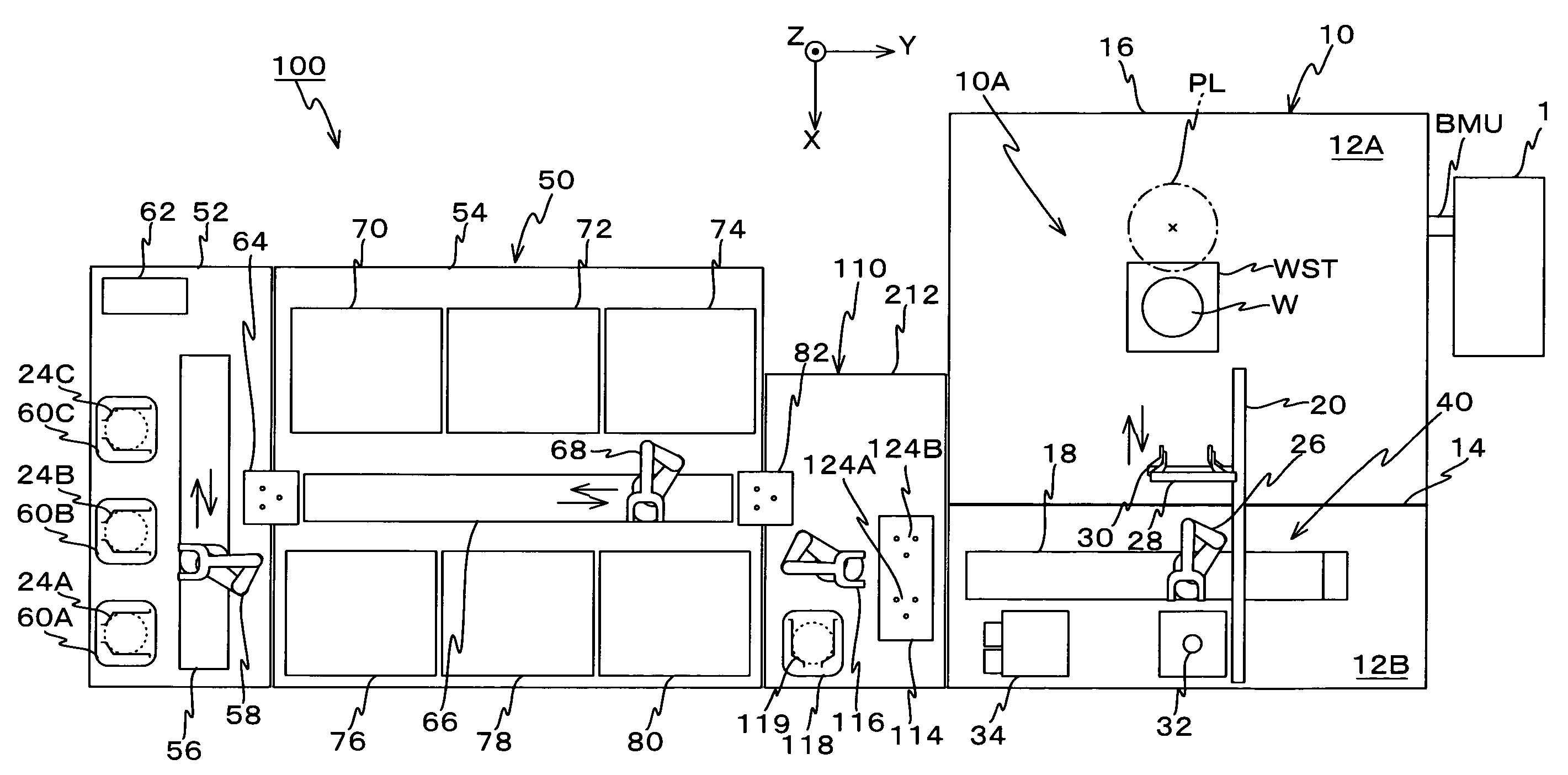
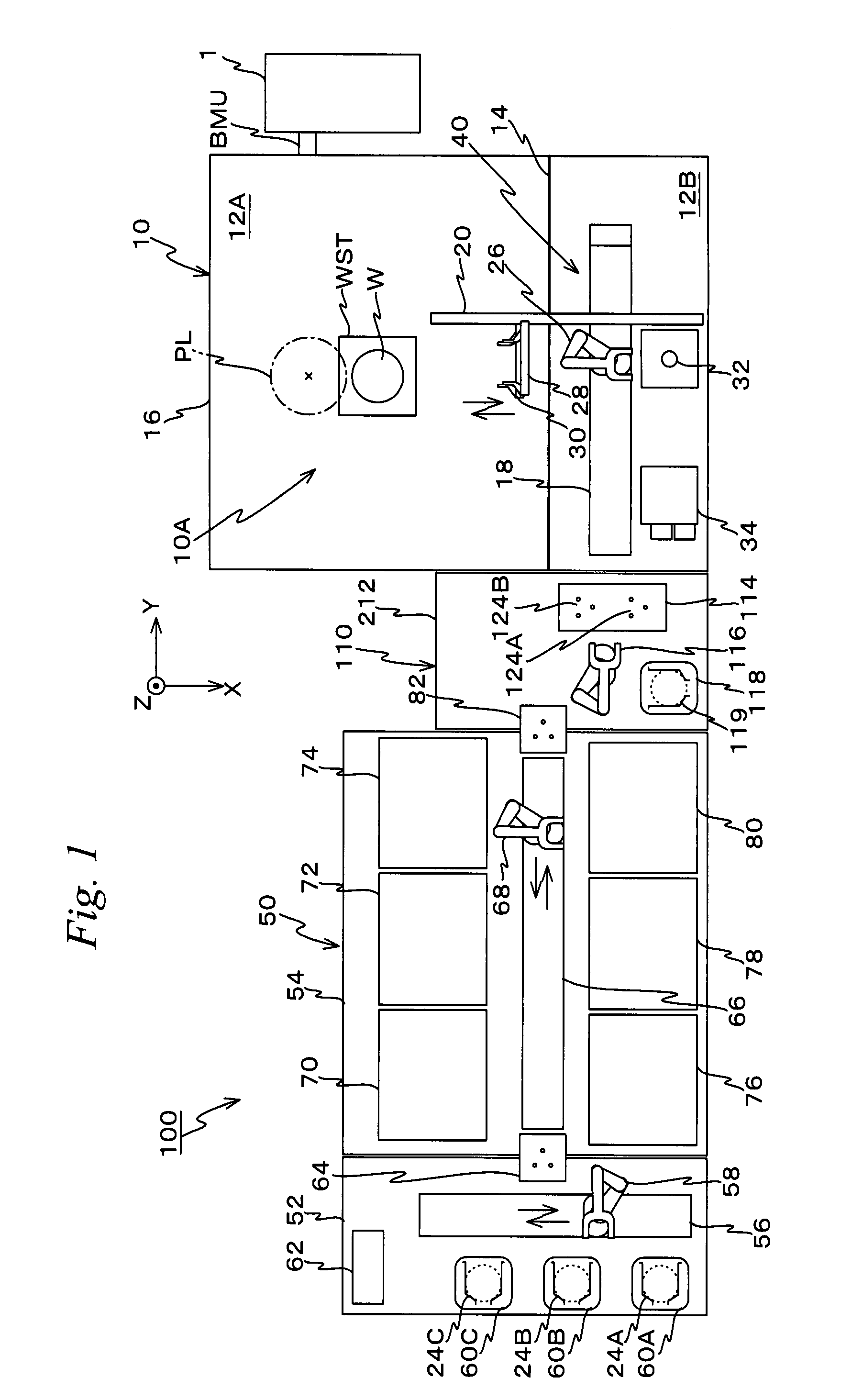
[0044]FIG. 1 is a planer view showing the configuration of a lithography system related to a first embodiment including an exposure apparatus and a substrate processing apparatus related to the present invention.

[0045]A lithograph system 100 shown in FIG. 1 is installed in a clean room. Lithography system 100 includes an exposure apparatus 10 installed on a floor surface of the clean room, and a C / D50 that is connected to a −Y side (left side in the page surface of FIG. 1) of exposure apparatus 10 via an inline interface section (hereinafter, referred to as an ‘inline I / F section) 100.

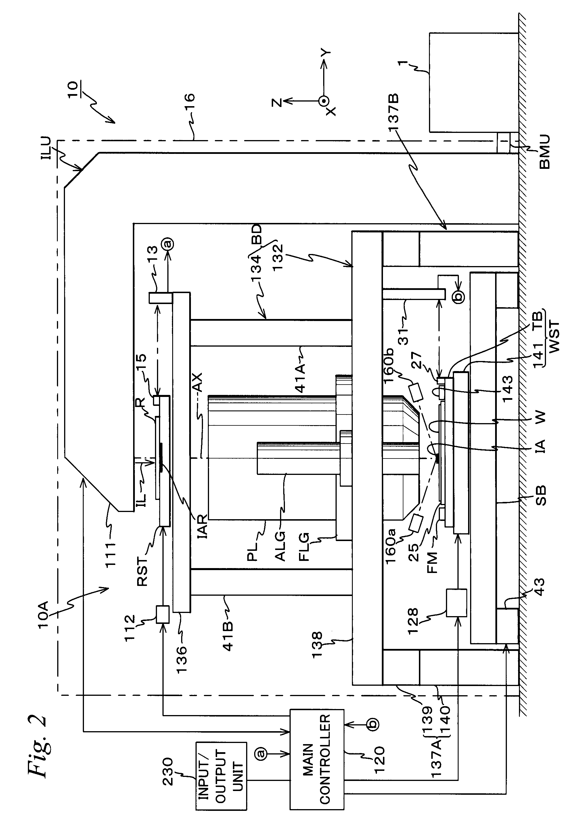
[0046]Exposure apparatus 10 includes a chamber 16 in which a partition wall 14 is arranged at a position that is slightly closer to a +X side from the center in an X-axis direction in FIG. 1, an exposure apparatus main section10A (portions other than a wafer stage WST and a projection optical system PL ...

second embodiment

[0184]Next, a second embodiment of the present invention will be described based on FIG. 4. Herein, with regard to the same or equivalent constituents as / to those of the first embodiment, the same reference codes will be used and the description will be omitted. A lithography system of the second embodiment is different from the first embodiment only in the configuration of a control system, and therefore the different point will be mainly explained in the following description.

[0185]FIG. 4 shows the configuration of a control system of the lithography system of the second embodiment in a block diagram.

[0186]As is shown in FIG. 4, the second embodiment has the characteristics that a host computer 90 is connected in common to coating / developing controller 62 on the C / D50 side and to main controller 120 of exposure apparatus 10. As a matter of course, also in the second embodiment, maintenance work items (including component replacement and the like) to be carried out in C / D50 and mai...


PUM


Abstract

An exposure apparatus is equipped with a main controller that decides an operation of the exposure apparatus based on information on maintenance from a C / D. Therefore, the main controller can decide to perform a specific operation, which is necessary for maintaining performance of the exposure apparatus and requires stop of the primary operation of the exposure apparatus, during maintenance of the C / D, that is, when the primary operation of the exposure apparatus has to be stopped by necessity, in parallel with the maintenance of the C / D. As a consequence, downtime of the exposure apparatus necessary for performing the specific operation can be decreased as a whole, which makes it possible to improve the operating rate without lowering apparatus performance of the exposure apparatus that is inline connected to a substrate processing apparatus.

Description

CROSS REFERENCE TO RELATED APPLICATIONS[0001]This application claims the benefit under 35 U.S.C. §371, of PCT International Application Number PCT / JP2005 / 015628, filed Aug. 29, 2005, and Japanese Application No. 2004-249395, filed Aug. 30, 2004 in Japan, the contents of which are incorporated herein by reference.TECHNICAL FIELD[0002]The present invention relates to exposure apparatuses, operation decision methods, substrate processing systems, maintenance management methods and device manufacturing methods, and more particularly, to an exposure apparatus that is inline connected to a substrate processing apparatus, an operation decision method in which an operation in the exposure apparatus is decided, a substrate processing system that is equipped with an exposure apparatus and a substrate processing apparatus that is inline connected to the exposure apparatus, a maintenance management method in which maintenance of each apparatus in the substrate processing system is managed, and ...

Claims


Application Information

Patent Timeline
Patent Type & Authority Patents(United States)
IPC IPC(8): G03B27/42G03B27/32G03D5/00G06F19/00
CPCH01L21/67225G03F7/70525G03F7/70975
Inventor SHIRATA, YOUSUKE
Owner NIKON CORP
Why Eureka
Try Eureka