Method, a language and a system for the definition and implementation of software solutions by using a visualizable computer executable modeling language

Active Publication Date: 2010-04-06
FIDELITY INFORMATION SERVICES LLC
View PDF20 Cites 62 Cited by
  • Summary
  • Abstract
  • Description
  • Claims
  • Application Information

AI Technical Summary

Benefits of technology

[0025]The system of the present invention enables a user to easily and intuitively visually define systems and processes that comprise software solutions otherwise characterized by system analysts and then implemented by professional software programmers, laboriously writing numerous lines of source code in one of the known high level programming languages, such as Java, C++, C, Visual Basic, etc. Instead, according to the present invention, the user visually defines the software solutions in the modeling language by means of the modeling environment, which actually replaces the lengthy procedure of writing a computer program. To complete the cycle, the runtime engine of the present invention executes the solution defined by means of the modeling language, thereby automatically enablin

Problems solved by technology

This approach results in a slow implementation process and suffers from maintenance problems due to the gap between the descriptive nature of the modeling language used for the design and the language required for the programming, where source code is used.
In addition, currently known modeling languages, such as UML, are themselves very complicated languages, the learning and mastering of which takes a very long time.
This approach results in high system complexity and maintenance problems resultin

Method used


Image

  • Method, a language and a system for the definition and implementation of software solutions by using a visualizable computer executable modeling language
  • Method, a language and a system for the definition and implementation of software solutions by using a visualizable computer executable modeling language
  • Method, a language and a system for the definition and implementation of software solutions by using a visualizable computer executable modeling language

Examples


Example

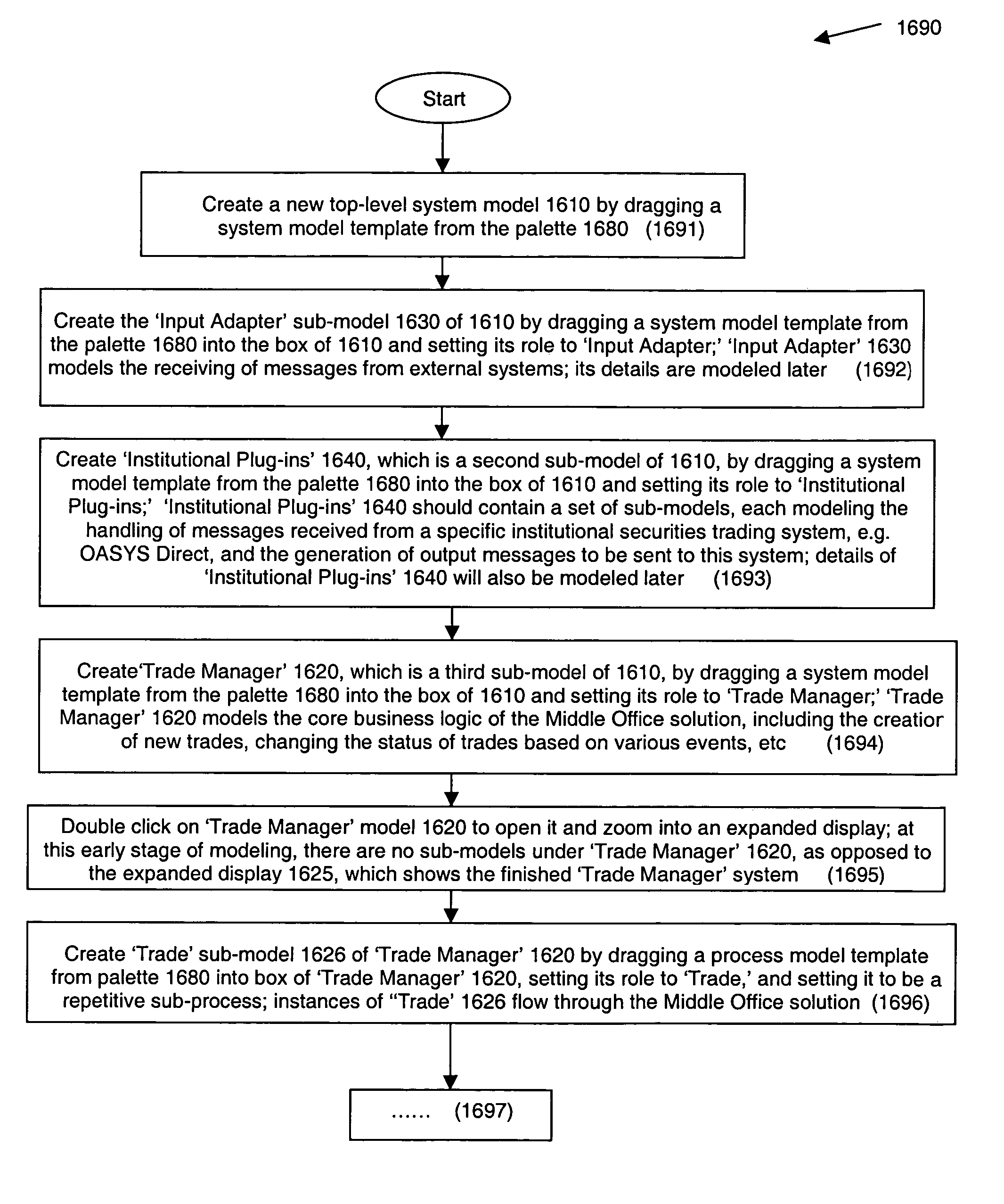
[0079]The invention will now be described inconnection with certain preferred embodiments with reference to the following illustrative figures so that it may be more fully understood. References to like numbers indicate like components in all of the figures. The elements of the invention are described in increasing complexity in FIGS. 1 through 14. However, to get an overview of the invention, reference may be first made to FIGS. 15, 16 and 16a, wherein a real-life example best illustrates the usage of the present invention for replacing the writing of source code for developing software applications.

[0080]The system of the present invention can be described as comprising three major elements: a visualizable computer executable modeling language for the definition of software solutions; a modeling environment for visually defining the software solutions in the modeling language; and a runtime engine that executes solutions defined in the modeling language.

[0081]The term “visualizabl...


PUM


Abstract

A software development platform, used to develop software applications substantially free of the need to write code. The platform includes a visualizable computer executable modeling language for the definition of software solutions. The platform also includes a visual modeling system comprising a visual modeling tool for users to develop software solutions using the modeling language, and a runtime engine software program that automatically executes the defined software solutions. The visualizable computer executable modeling language system enables defining each application by a set of: process models, each of which may contain any number of sub process model; input and output slots; data models, each of which may contain any number of sub data models; and flow rules applicable to connect pairs of slots, data models and sub-data models, thereby defining both data flow and process flow, wherein the sets of process models, slots, data models and flow rules are arranged in a structural hierarchy conforming to a set of rigid composition rules.

Description

FIELD OF THE INVENTION[0001]The present invention relates to methods and languages for developing software solutions. More particularly, the present invention relates to a method, a language and a system for overcoming the need to write computer source code in order to develop software applications.BACKGROUND OF THE INVENTION[0002]Originally computers utilized low level technical notation and encoding. Gradually, more visually oriented and intuitive computer interfaces were developed. Such developments included the video monitor, use of icons and object-orientation incorporated in Visual Basic™, Visual C++ and Java™. The development of graphical user interfaces for developers began to reshape the programming process.[0003]The concept of an application framework means that programmers start with working application code and basic user interface elements in place. Application development frameworks attempt to enable more simplified processing of information through the various levels ...

Claims


Application Information

Patent Timeline
IPC IPC(8): G06F9/44G06F3/00G06F3/048G06FG06F1/00
CPCG06F8/34
Inventor BRONICKI, YOUVALBRANDES, OFERRASKIN, YISHAYSHAKED, YARIVSZEKELY, SMADAR
Owner FIDELITY INFORMATION SERVICES LLC
Why Eureka
Try Eureka