Method and device for fabricating aerogels and aerogel monoliths obtained thereby

a technology of aerogels and monoliths, which is applied in the direction of fluorescence/phosphorescence, instruments, silicon compounds, etc., can solve the problems of affecting the development of aerogel materials in commercial applications, affecting the development of aerogel materials, and affecting etc., and achieves the effects of improving the adaptability to large-scale assembly-line fabrication applications, and improving the quality of aerogels

Active Publication Date: 2008-06-10
UNION COLLEGE
View PDF15 Cites 13 Cited by
  • Summary
  • Abstract
  • Description
  • Claims
  • Application Information

AI Technical Summary

Benefits of technology

[0014]A second aspect of the present invention relates to a method for rapidly producing aerogels that includes the steps of: heating and applying external restraining force to a sealed vessel that contains therein a gel precursor solution or a pre-formed gel that at least partially fills the internal volume of the sealed vessel, said heating and applying external restraining force being carried out without substantial venting of the vessel and thereby confining physical expansion of the gel or gel precursor; and controllably releasing the external restraining force applied to the vessel, thereby allowing for venting and release of internal pressure to form the aerogel.
[0019]The process of the present invention offers a number of distinct advantages over existing techniques. The process is fast, simple, and easily automated, which may make it more amenable to large-scale assembly-line fabrication applications. The process is also safe. The hydraulic press provides a restraining force capable of (1) containing the internal pressure and (2) controllably releasing excess pressure. The only pressurized volume is the gel itself, not an entire hydrostatic volume as is the case when using an autoclave or an external hydrostatic pressure, as in the RSCE process. Additional safety concerns associated with the release of supercritical alcohol can be alleviated by encasing the inter-platen working area and flushing the working area with a nitrogen purge to eliminate the possibility of auto-ignition of hot solvent (e.g., methanol) should it escape from the mold and mix with air. By doping the aerogel precursors with fluorescent dyes or coordination complexes, it is possible to prepare chemical sensors that are cost- and time-effective, require little synthetic work, and can be easily adapted for simultaneous use with many of the current aerogel systems.

Problems solved by technology

At present, aerogel materials are difficult and expensive to manufacture.
This manufacturing complexity has limited their development in commercial applications.
The primary challenge in the fabrication of an aerogel is to prevent the collapse of the porous structure during the drying phase.
More difficult to control, however, are the capillary stresses from surface tension that, for the nanoscale pore structure, are strong enough to cause structural collapse.
As the sol-gel dries, these capillary forces can result in significant fracture to the structure.
These techniques have been used successfully in the fabrication of aerogel films, but have had limited success for aerogel monoliths.
The main limitations of this technique are the difficulties associated with obtaining the high temperatures necessary to reach the critical point of the alcohol solvent, as well as the safety concerns with operating the pressure vessel at those conditions.
Because the critical pressure requirement is not changed significantly, this process still requires the use of thick pressure vessels and places practical limitations on the maximum size of the aerogel.
Even if a pressure vessel were available to contain a large monolith, the solvent exchange could take weeks to complete, depending on the size of the monolith.
For the fabrication of monolithic pieces, however, this technique has yet to prove reliable.
Conventional supercritical extraction has been used extensively in the fabrication of very large aerogel monoliths, however it can take days to weeks to make them, and the required multiple steps make the process complicated.

Method used


Image

  • Method and device for fabricating aerogels and aerogel monoliths obtained thereby
  • Method and device for fabricating aerogels and aerogel monoliths obtained thereby
  • Method and device for fabricating aerogels and aerogel monoliths obtained thereby

Examples


example 1

System for Aerogel Fabrication

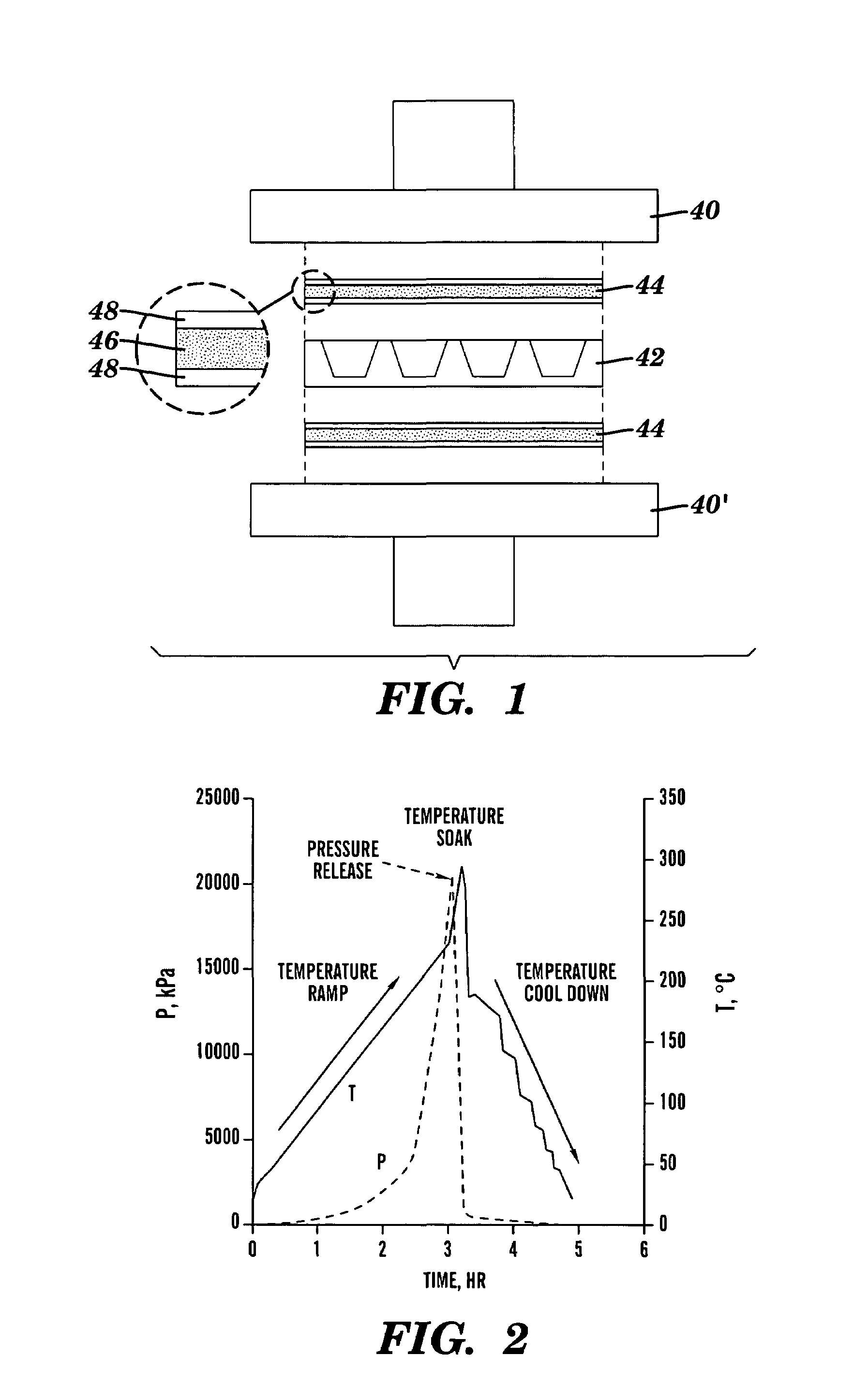
[0066]Referring to FIG. 1, equipment used to fabricate the aerogel monoliths by the new fast supercritical extraction technique of the present invention includes a 50-ton hydraulic hot press (having upper and lower press plates 40, 40′), a stainless-steel mold 42, and a high-temperature seal 44 formed of a graphite gasket 46 sandwiched between sheets of Kapton™ film 46. By way of example, the mold 42 is fabricated from a 10×10×2 cm3 thick piece of stainless steel (see FIG. 1). Sixteen 2.2 cm diameter, 1.7 cm-deep holes (with a 7° taper) are spaced uniformly across the plate. The surface was ground flat to ensure a good seal between the gasket and the mold.

example 2

Fabrication of Aerogels

[0067]The system described in Example 1 above was used to prepare aerogels.

[0068]The one-step fabrication process entails two main phases, both of which take place inside of the mold during a continuous process. The first phase is to polymerize silica to form a sol-gel, and the second phase is to safely evacuate the water and alcohol solution. Initially, the chemical precursors for the aerogel were mixed and poured into the mold. For a tetramethoxysilane-derived (TMOS) aerogel, these precursors are TMOS, deionized water, methanol, and ammonium hydroxide with molar ratios TMOS:MeOH:H2O:NH4OH of 1.0:12.0:4.0:3.7×10⁻³.

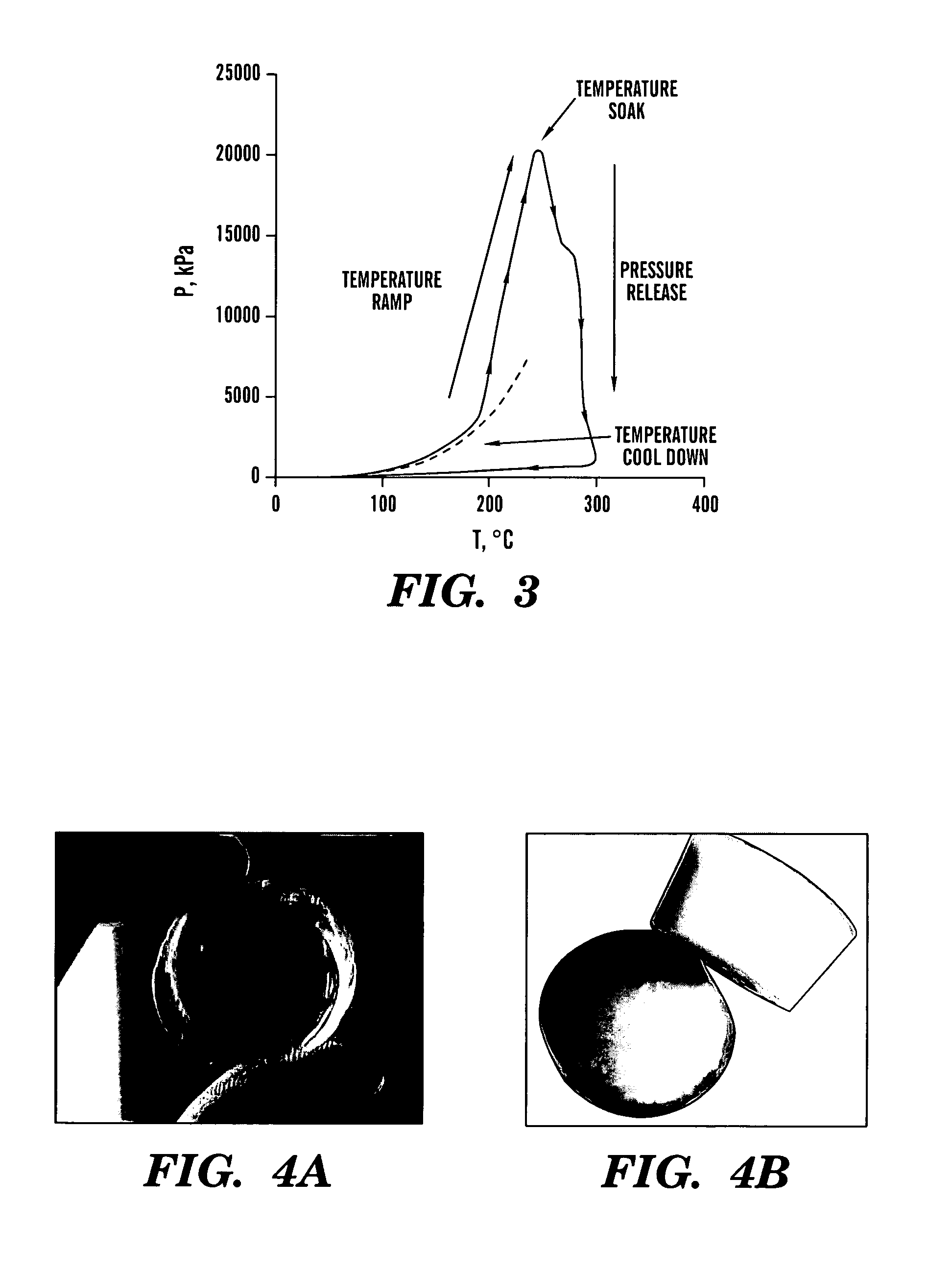
[0069]The mold is placed in the hydraulic hot press and the processing begins by applying and holding a 75 kN restraining force. Typically, a temperature ramp of 1.25° C.·min−1 is applied to heat the mold from ambient temperature to a supercritical temperature (˜265−300° C.). The internal pressure of the mold increases as a result of the temperature...

example 3

Characterization of Aerogels

[0075]Using the procedure described in Example 2, several monolithic cylindrical aerogel samples were prepared. Sample aerogel monoliths are shown in FIGS. 4A-B.

[0076]Bulk density measurements were made using a caliper and mass balance. Values as low as 0.066 g·cm−3 were measured.

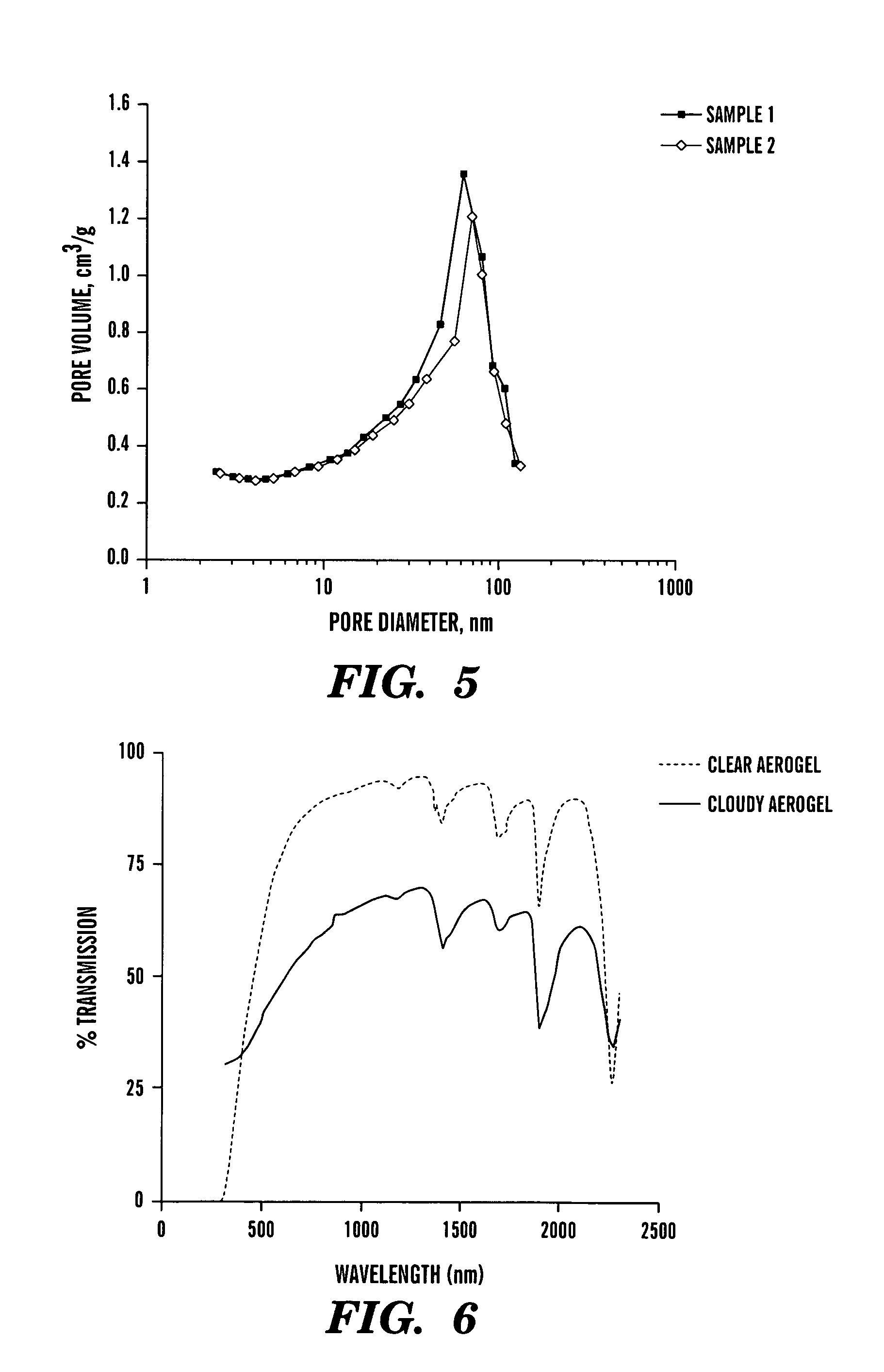
[0077]The aerogel pore-size data were characterized using a Micromeritics ASAP 2010 Nitrogen Adsorption system (Micromeritics Instrument Corporation). Samples were outgassed for 5 hours at 200° C. prior to analysis. A 5-point Brunauer-Emmett-Teller (BET) analysis was used to determine surface area. Mesopore distributions were determined from the desorption branch of the nitrogen isotherm using the Barrett-Joyner-Halenda (BJH) method. The BET surface areas were found to be 320 m2·g−1, and the BJH desorption average pore size was found to be about 15 nm. Incremental pore volume was found to peak at 68 nm. FIG. 5 presents the desorption pore-size distribution. The 320 m2·g−1 surface...


PUM

PropertyMeasurementUnit
dwell temperatureaaaaaaaaaa
forceaaaaaaaaaa
external restraining forceaaaaaaaaaa

Abstract

Method and devices for rapidly fabricating monolithic aerogels, including aerogels containing chemical sensing agents, are disclosed. The method involves providing a gel precursor solution or a pre-formed gel in a sealed vessel with the gel or gel precursor at least partially filling the internal volume of the vessel and the sealed vessel being positioned between opposed plates of a hot press; heating and applying a restraining force to the sealed vessel via the hot press plates (where the restraining force is sufficient to minimize substantial venting of the vessel); and then controllably releasing the applied restraining force under conditions effective to form the aerogel. A preferred device for practicing the method is in the form of a hot press having upper and lower press plates, and a mold positioned between the upper and lower plates. Doped aerogel monoliths and their use as chemical sensors are also described.

Description

[0001]This application claims the priority benefit of U.S. Provisional Patent Application Ser. No. 60 / 498,329, filed Aug. 26, 2003, which is hereby incorporated by reference in its entirety.STATEMENT OF GOVERNMENT SPONSORSHIP[0002]The present invention was made at with funding received from the National Science Foundation under grant CTS-0216153. The U.S. government has certain rights in this invention.FIELD OF THE INVENTION[0003]The present invention relates generally to methods and devices for fabricating aerogels, monolithic aerogel products, and their use.BACKGROUND OF THE INVENTION[0004]Silicate precursors, such as tetramethoxysilane (Si(OCH3)4, “TMOS”), are commonly used to produce porous silica glasses (Brinker et al., Sol-Gel Science, Academic Press, New York (1990)). The resultant materials are highly crosslinked polymer matrices with solvent filled pore spaces. This solvent can be evacuated from the pore-matrix either by evaporation or by supercritical extraction; the two ...

Claims


Application Information

Patent Timeline
Patent Type & Authority Patents(United States)
IPC IPC(8): C08J9/28C08J9/00B01J13/00C01B33/158G01N21/64
CPCB01J13/0091C01B33/1585G01N21/6428G01N21/645
Inventor GAUTHIER, BEN M.ANDERSON, ANN M.BAKRANIA, SMITESHMAHONY, MARY K.BUCINELL, RONALD B.
Owner UNION COLLEGE
Why Eureka
Try Eureka