
Porosity reference standard utilizing one or more hollow, non-cylindrical shafts

a reference standard and non-cylindrical technology, applied in the direction of instruments, specific gravity measurement, structural/machine measurement, etc., can solve the problem of difficulty in tying detection and quantification of porosity

Inactive Publication Date: 2010-04-13
THE BOEING CO
View PDF68 Cites 7 Cited by
  • Summary
  • Abstract
  • Description
  • Claims
  • Application Information

AI Technical Summary

Benefits of technology

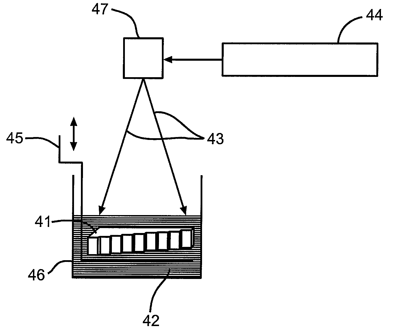
The invention provides an ultrasonic inspection reference standard for composite materials with porosity. This reference standard is made of a hollow, non-spherical shaft made from a fiber-free polymer resin. The invention also provides an ultrasonic inspection process for composite materials with porosity using this reference standard. The technical effect of this invention is to provide a reliable and accurate method for inspecting composite parts with porosity using ultrasonic techniques.

Problems solved by technology

It is difficult however to tie detection and quantification of porosity to a representative planar defect reference standard without the introduction of defects that mimic porosity.

Method used


Image

  • Porosity reference standard utilizing one or more hollow, non-cylindrical shafts
  • Porosity reference standard utilizing one or more hollow, non-cylindrical shafts
  • Porosity reference standard utilizing one or more hollow, non-cylindrical shafts

Examples


Embodiment Construction

[0025]The following detailed description is of the best currently contemplated modes of carrying out the invention. The description is not to be taken in a limiting sense, but is made merely for the purpose of illustrating the general principles of the invention, since the scope of the invention is best defined by the appended claims.

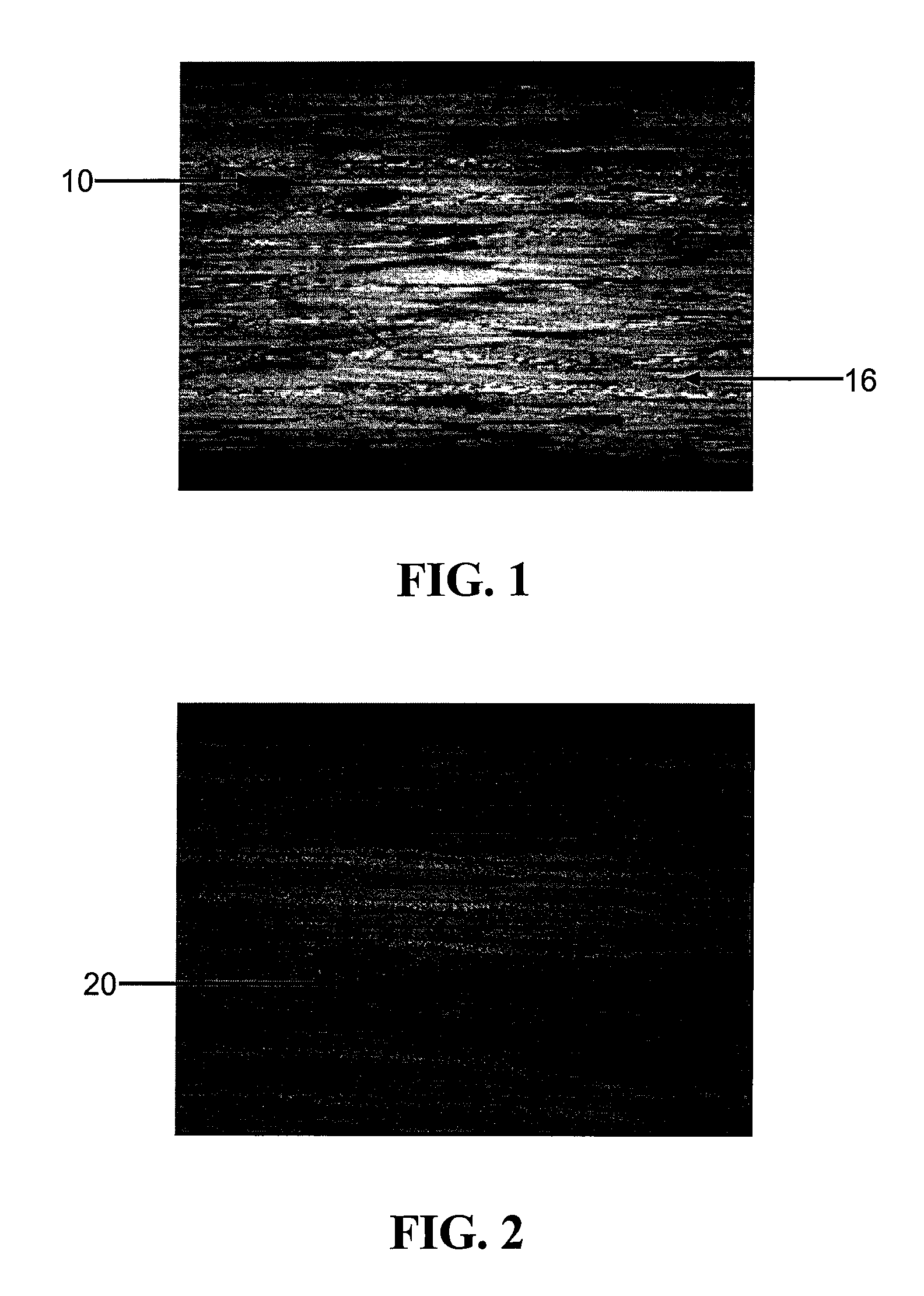
[0026]Composite laminates consist of two primary constituents including a fiber, and a resin matrix that bonds the fibers together. The fiber is typically graphite. Porosity in composite laminates is an unwanted product of the manufacturing cure cycle and is characterized by voids or a lack of resin within the laminate. FIG. 1 depicts a photomicrograph of a composite laminate with areas of porosity 10 shown as elliptical shapes that appear darker than the surrounding non-porous areas 16. The morphology and distribution of the porosity vary depending on a number of processing variables. The size of porosity also varies from relatively small diameters of ...


PUM

PropertyMeasurementUnit
porosityaaaaaaaaaa
ultrasonic inspectionaaaaaaaaaa
porosityaaaaaaaaaa

Abstract

The invention relates to pseudo porosity standards, and methods for their manufacture and use, which may substantially mimic the effect porosity has on ultrasonic sound as it passes through a composite laminate. An ultrasonic inspection reference standard for composite materials having porosity may include a member having at least one thickness. The member may be defined by at least one hollow, non-spherical shaft. The member may be manufactured from a fiber-free polymer resin using a stereo lithography process. The non-spherical shaft may scatter and attenuate ultrasonic energy. The reference standard may replace more costly, porous, fiber-reinforced, composite reference standards in the aircraft industry and in other non-aircraft applications.

Description

CROSS-REFERENCE TO RELATED APPLICATIONS[0001]This application is a continuation-in-part (CIP) of U.S. patent application Ser. No. 11 / 281,116, filed on Nov. 17, 2005, titled “Porosity Reference Standard Utilizing a Mesh”.BACKGROUND OF THE INVENTION[0002]Composite laminate reference standards are employed when performing ultrasonic inspection of composite laminate materials. They are used to aid in the detection of planer defects such as delaminations, foreign material, and the detection and quantification of porosity. A relationship exists between the strength of a composite laminate and the presence of defect conditions. This relationship is established in the course of effects-of-defects programs that look at the strength degradation of materials as a result of defects. Composite reference standards are currently manufactured with representative planar conditions to aid in the detection of delaminations and foreign material. It is difficult however to tie detection and quantificati...

Claims


Application Information

Patent Timeline
Patent Type & Authority Patents(United States)
IPC IPC(8): G01N29/30
CPCG01N29/30G01N2291/015G01N2291/2694G01N2291/0289G01N2291/0231B33Y80/00B33Y70/00
Inventor ENGELBART, ROGER W.VACCARO, CHRISTOPHER M.BEISIEGEL, APRIL L.
Owner THE BOEING CO
Learn More