Engine

a technology of air-cooled engines and cylinder heads, which is applied in the direction of machines/engines, combustion-air/fuel-air treatment, mechanical equipment, etc., can solve the problems of insufficient cooling of parts of cylinders at high temperatures, insufficient cooling of parts of cylinders, and reduced total amount of cooling air passing in the cylinder head, so as to improve the cooling efficiency of the cylinder head, the effect of reducing the cost of the increas

Inactive Publication Date: 2010-04-13
YANMAR POWER TECHNOLOGY CO LTD
View PDF14 Cites 6 Cited by
  • Summary
  • Abstract
  • Description
  • Claims
  • Application Information

AI Technical Summary

Benefits of technology

[0020]With regard to an engine according to the present invention, a cooling fan is provided at one end of a crankshaft, and cooling air from the cooling fan is guided to a cylinder head so as to cool the cylinder head, an intake manifold is arranged above the cooling fan, a duct is provided at the lateral center of the intake manifold so as to suck air from an air cleaner, cooling air is sent from both sides of the duct to an intake valve, an exhaust valve and an injection nozzle arranged in the cylinder head, and a shielding plate is provided at one of lateral sides of the duct. Accordingly, the amount of cooling air flowing in the other is increased. Therefore, a large amount of cooling air is sent to the intake valve, the exhaust valve and the injection nozzle, thereby improving the cooling efficiency of the cylinder head. Furthermore, the amount of cooling air flowing in one of the cooling air passages can be made larger than that flowing in the other cooling air passage easily only by providing the shielding plate, thereby minimizing any increase in cost.
[0021]With regard to the engine according to the present invention, the shielding plate is constructed integrally with the intake manifold. Accordingly, the intake manifold can be constructed cheaply and the number of assembly processes thereof can be reduced.
[0022]With regard to the engine according to the present invention, the shielding plate is constructed integrally with the intake manifold and the air cleaner. Accordingly, the shielding plate, the intake manifold and the air cleaner body can be assembled at once cheaply.
[0023]With regard to the engine according to the present invention, a gap is provided between the tip of the shielding plate and the cylinder head. Accordingly, a part of cooling air enters the cooling air passage shielded by the shielding plate so that the cylinder head is cooled by both cooling air passages.
[0024]With regard to the engine according to the present invention, the shielding plate is arranged substantially perpendicularly to a tangential line of rotation locus of the cooling fan. Accordingly, the shield effect of the shielding plate is improved.
[0025]With regard to the engine according to the present invention, the shielding plate is arranged oppositely to a muffler arranged at a side of the cylinder head. Accordingly, with regard to the left and right cooling air passages formed in the cylinder head, the amount of cooling air in the cooling air passage at the side of the muffler is larger, whereby the cylinder head is cooled efficiently.

Problems solved by technology

However, in this case, a part of the cooling air is discharged through the gap of the guide member so that the total amount of the cooling air passing in the cylinder head is reduced, whereby the efficient cooling effect cannot be obtained.
However, in this case, each part of the cylinder is cooled uniformly, whereby the part of the cylinder at which the temperature is high is not cooled sufficiently.

Method used


Image

  • Engine
  • Engine
  • Engine

Examples


Embodiment Construction

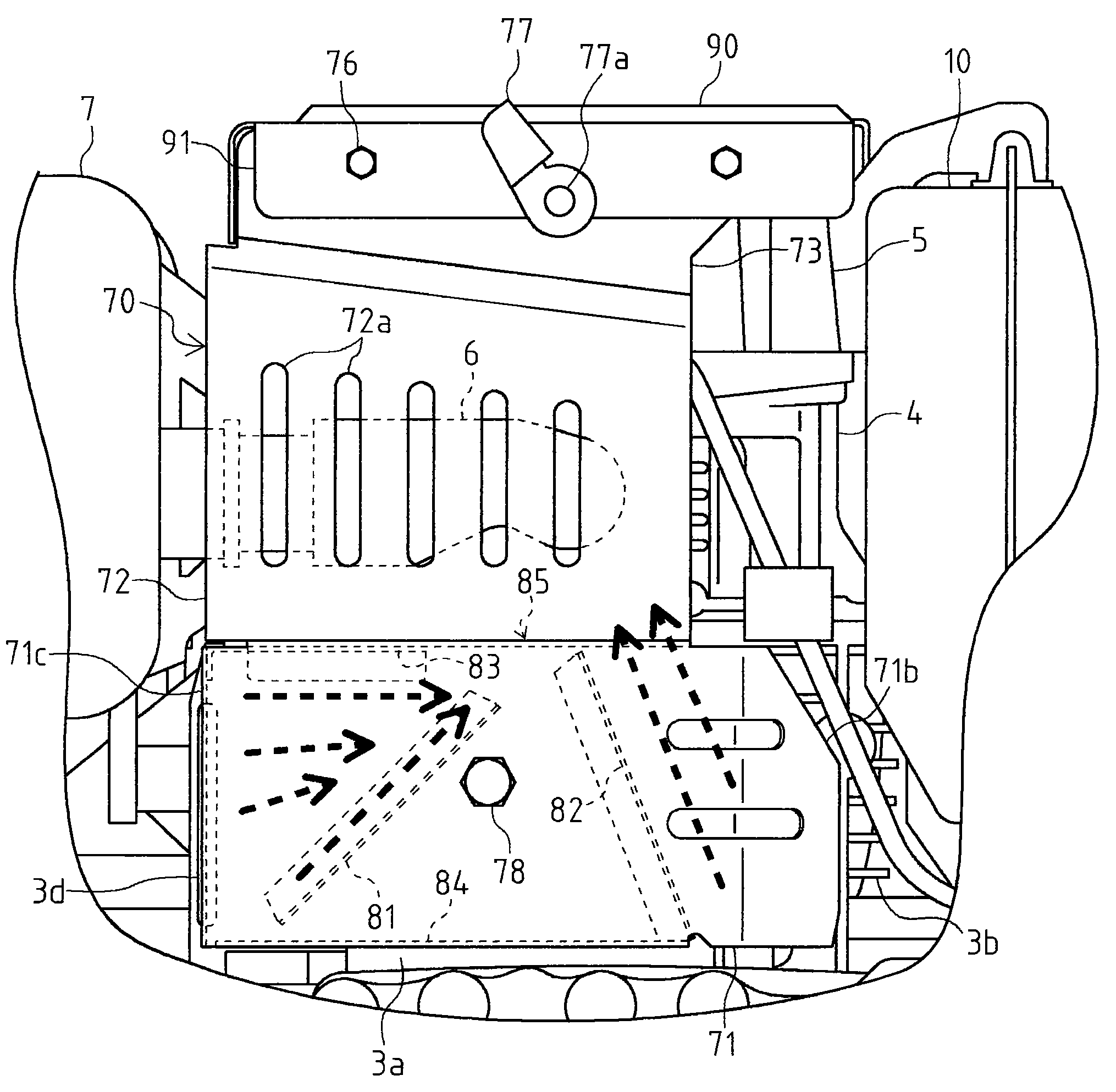
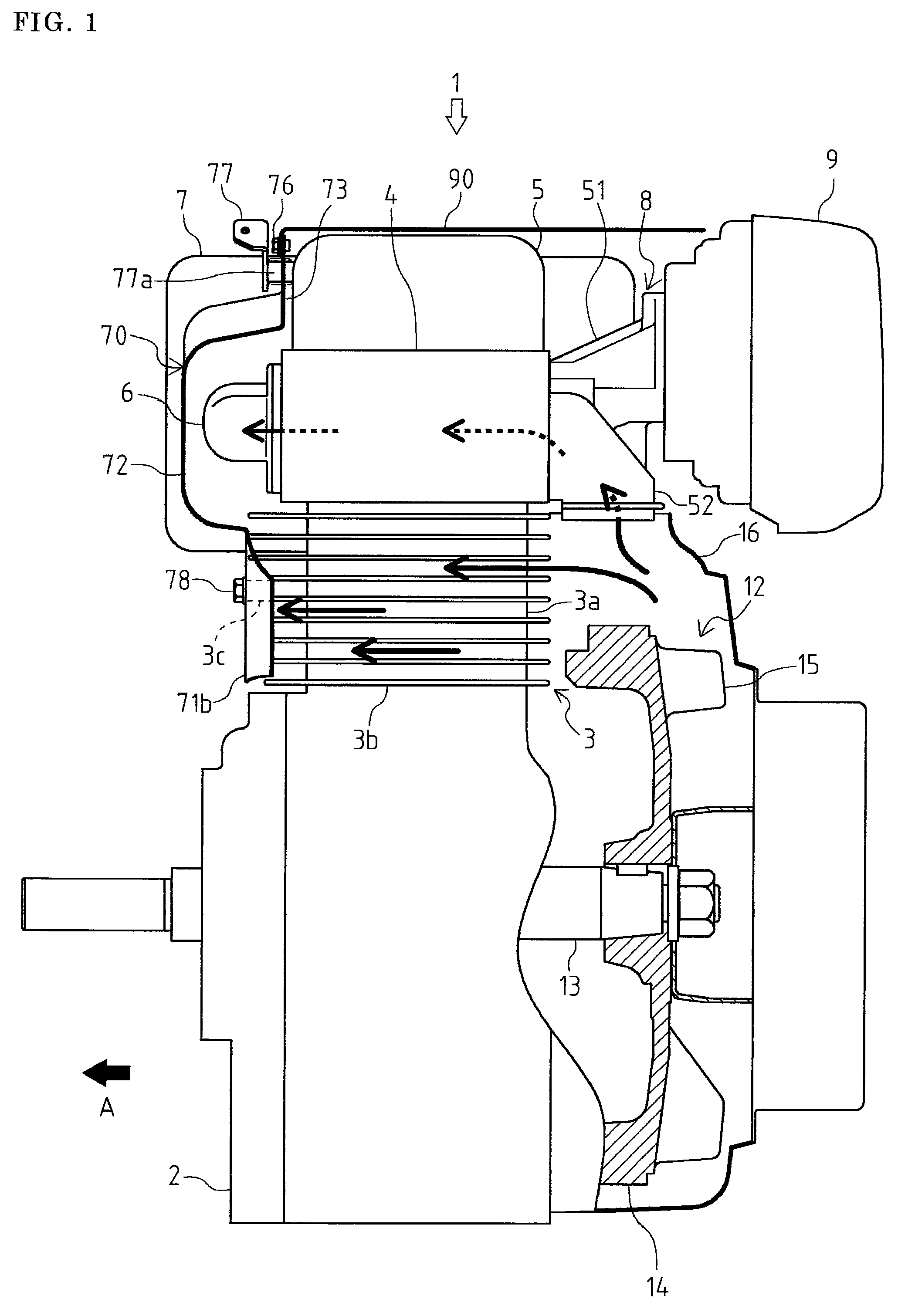
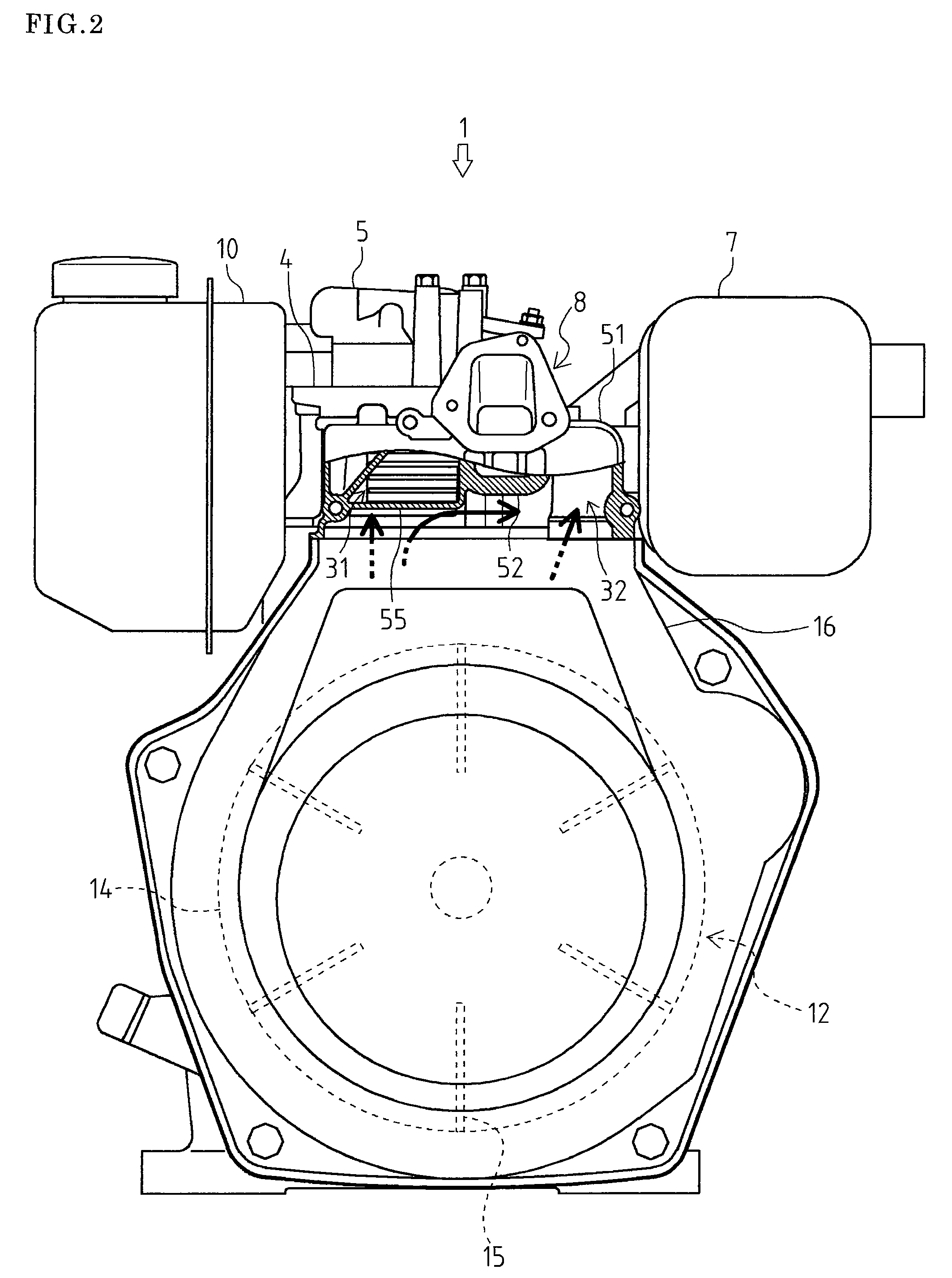
[0060]As shown in FIGS. 1 and 2, an engine 1 comprises a crankcase 2 and a cylinder block 3, and a cylinder head 4 is disposed on a cylinder 3a formed in the cylinder block 3. A bonnet 5 is attached on the cylinder head 4. In addition, with regard to this embodiment, the direction of an arrow A is regarded as the forward direction of the engine 1. The arrows in FIGS. 1, 2 and 8 indicate the flow of cooling air.

[0061]An exhaust manifold 6 is attached through a flange to the front surface of the cylinder head 4, and the tip of the exhaust manifold 6 is connected to a muffler 7 arranged at the right of the cylinder head 4. On the other hand, an intake manifold 8 is attached to the rear surface of the cylinder head 4, and the tip of the intake manifold 8 is connected to an air cleaner 9 arranged at the rear of the cylinder head 4.

[0062]A cooling fan 12 is arranged below the air cleaner 9. The cooling fan 12 comprises a flywheel 14 fixed to an end of a crankshaft 13 extended from the cra...


PUM


Abstract

The purpose of the present invention is to improve cooling efficiency of a cylinder head of an air-cooled engine. With regard to the construction that a cooling fan is provided at one of ends of a crankshaft, and cooling air from the cooling fan is guided to a cylinder head 4 so as to cool the cylinder head 4, an intake manifold 8 is arranged above the cooling fan, a duct 51 is provided at the lateral center of the intake manifold 8 so as to suck air from an air cleaner, cooling air is sent from both sides of the duct 51 to an intake valve, an exhaust valve and an injection nozzle arranged in the cylinder head 4, and a shielding plate 55 is provided at one of lateral sides of the duct 51.

Description

TECHNICAL FIELD[0001]The present invention relates to an air-cooled engine. Especially, the present invention relates to cooling construction of a cylinder head and a cylinder of the engine.BACKGROUND ART[0002]Conventionally, there is well known an air-cooled engine in which equipment, such as a muffler, a fuel tank and an air cleaner, is arranged at a side of a cylinder head, a cooling air from a cooling fan provided on one side of a cylinder is guided into the cylinder head from the side of the cooling fan, and the cooling air passes through a cooling air passage formed in the cylinder head and is discharged at the opposite side (for example, see the Patent Literature 1), and an air-cooled engine that the cooling air is sent to the outside of the cylinder opposite to the cooling fan so as to cool the cylinder (for example, see the Patent Literature 2).[0003]With regard to the cooling construction of the cylinder head shown in the Patent Literature 1, a first induction port and a s...

Claims


Application Information

Patent Timeline
Patent Type & Authority Patents(United States)
IPC IPC(8): F01P1/02
CPCF01P1/02F01P1/08F01P1/10F01P5/06F02F1/28F02M31/145F02M35/10144F02M35/1017F02M35/10262F02M35/06Y02T10/14Y02T10/146Y02T10/126Y02T10/12F02B63/00F02F1/34
Inventor SAGARA, MASASHIKANAZU, YASUHIROYOSHII, MASAMI
Owner YANMAR POWER TECHNOLOGY CO LTD
Why Eureka
Try Eureka