Large arbor fly fishing reel, spool, drag and ventilation system

a technology of drag adjustment and large arbor, which is applied in the field of large arbor fly fishing reel, can solve the problems of difficult to use this drag adjustment system for a dynamic drag adjustment under fish fighting conditions, difficult to approach and operate, and the same drawback is typical, so as to improve the operation ability, improve the ventilation effect, and reduce the weight

Inactive Publication Date: 2010-04-13
CHIVAROV GEORGI
View PDF15 Cites 10 Cited by
  • Summary
  • Abstract
  • Description
  • Claims
  • Application Information

AI Technical Summary

Benefits of technology

[0008]The object of the present invention is to provide an improved fly fishing reel, spool, drag and ventilation system. A particular aim of the present inventors is to provide an anti-reverse fly reel of a simple assembly, lower weight, better ventilation, after all an enhanced operation ability allowing a simple by-instinct- and safety-of-line-control of drag and retrieve, and all this with a minimum number of parts.

Problems solved by technology

If additional drag is necessary for fighting the fish, the angler might try to re-adjust the drag knob which however, because of the fast rotating spool and crank knob is less appropriate than palming the reel spool.
In practice the re-tightening of the drag happens mostly on-purpose when fighting a fish, which is a tricky exercise considering the fact, that drag knobs or wheels are usually arranged behind the handle and close to the rotating front spool wall and thus, difficult to approach and operate.
However, since it requires a hand move being different from that natural one for winding in line, it is difficult to use this drag system also for a dynamic drag adjustment under fish fighting conditions.
The same drawback is typical for another known modification of such reel where the drag force can be dynamically altered by squeezing the crank knob.
Besides being complicated, this reel requires the angler to re-open and re-tighten—in this case the drag offset mechanism—every time he changes between the light drag position for paying out line from the spool and a heavy drag position for a ready-to-fight mode.
Since both the drag knob and the offset mechanism are located on the backside of the reel, they are useful in the practice only as drag preset means, whereas a dynamically controllable drag change is difficult to perform.
Therefore, the handle torque necessary for winding in a fighting fish causes a tremendous drag increase beyond the strength of the strongest line, and even more far away from the value actually necessary in order to frictionally couple the handle with the spool.
Although this alleviates to some extent the problem of escaping from the direct drive mode in case of a sudden fish run on the one side, it makes a sensible dynamic drag control over a reasonable rotation angle of the handle difficult on the other side.
Thus, fighting a fish with this reel requires either the well known palming of the spool or a parallel drag force setting by its drag wheel which—because being hidden behind the handle—is difficult to approach and operate.

Method used


Image

  • Large arbor fly fishing reel, spool, drag and ventilation system
  • Large arbor fly fishing reel, spool, drag and ventilation system
  • Large arbor fly fishing reel, spool, drag and ventilation system

Examples


1st embodiment

1st Embodiment

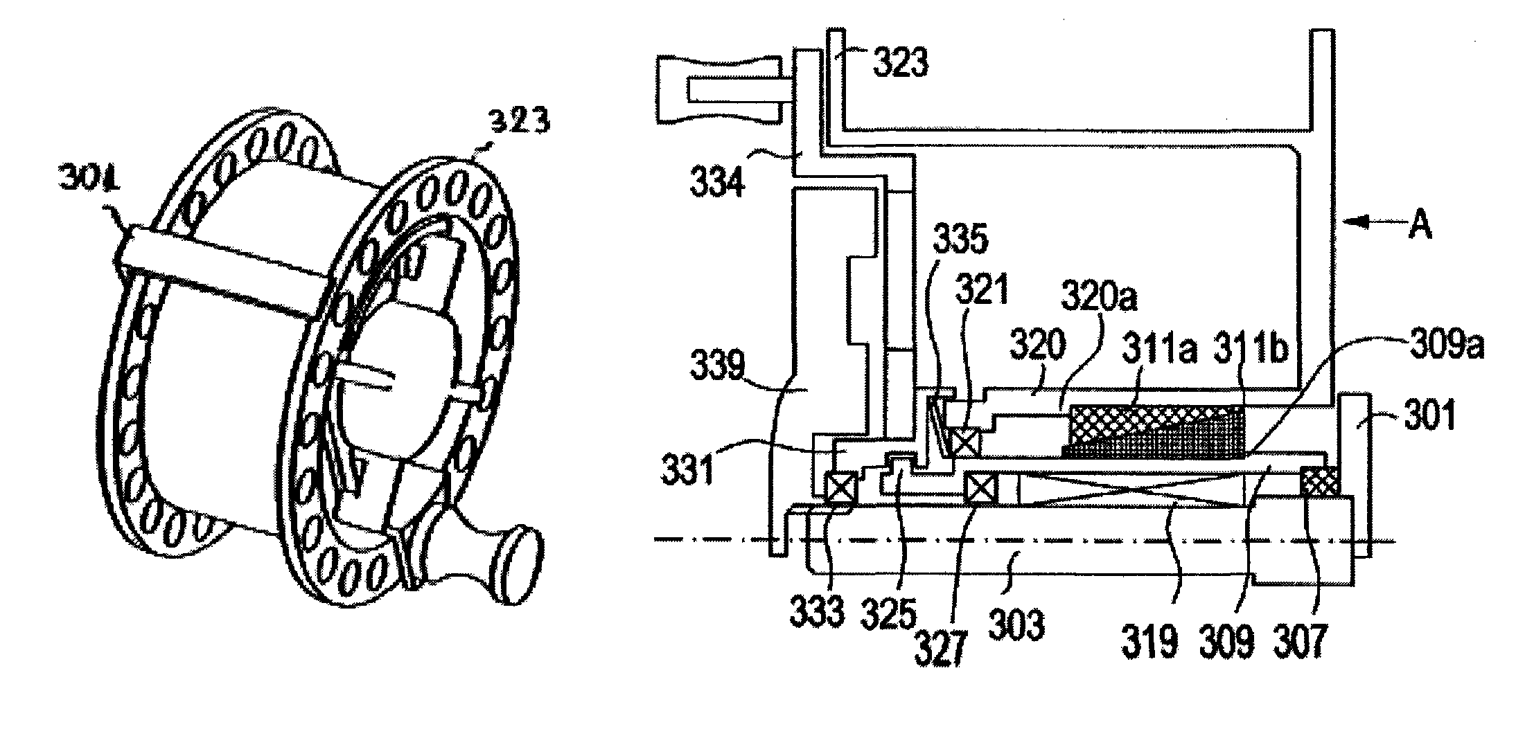
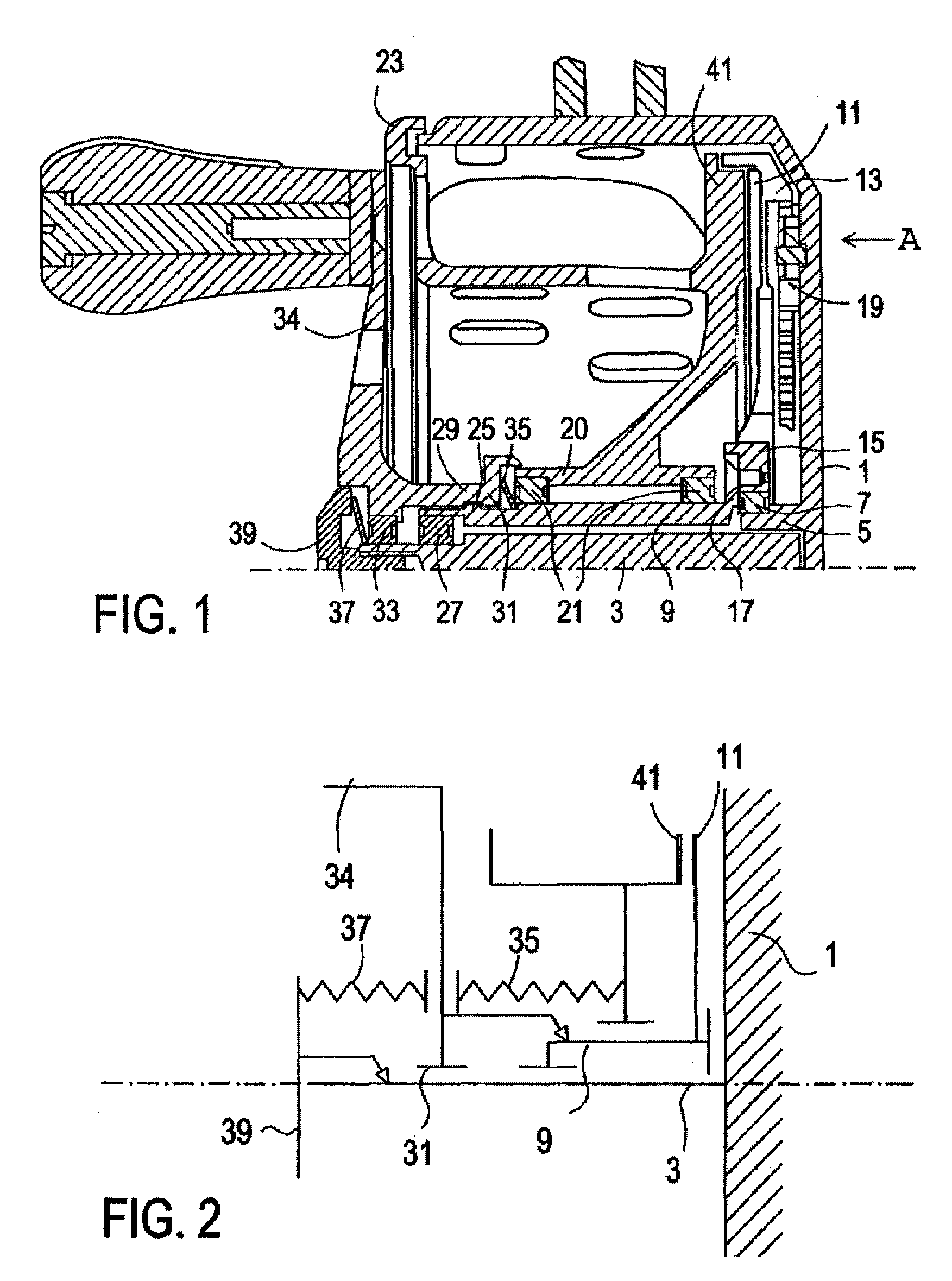
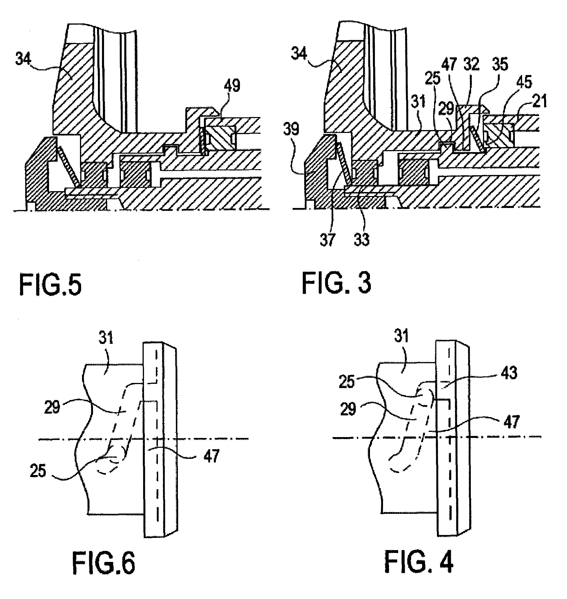
[0050]As shown in FIG. 1 a fly reel according to a first embodiment of the present invention has a frame 1 carrying a shaft 3 fixedly connected to the frame. For this purpose the shaft 3 is pressed into a collar portion 5 of the frame 1. On the outer circumference of the collar portion 5 there is mounted a roller bearing 7 supporting a carrying sleeve 9 provided with a drag ring 13 carrying a drag lining 11. The inner portion of the drag ring 13 is fixed by screws to a flange portion 17 of the carrying sleeve 9. Between the drag ring 13 and the frame 1 there is provided a free-running mechanism 19 which allows a free rotation of the drag ring 13 together with the carrying sleeve 9 in a clockwise direction—a shown in the direction of the arrow A in FIG. 1—but blocks a reverse rotation of the carrying sleeve in the opposite direction. Particularities of the free-running mechanism 19 can be derived from the U.S. Pat. No. 6,513,743 B1 which is incorporated herewith by refe...

2nd embodiment

2nd Embodiment

[0057]The second embodiment shown in the FIGS. 7 to 10 is substantially identical to the first embodiment, which is the reason why corresponding elements of these embodiments are designated by corresponding reference signs. The second embodiment comprises different modifications of particular functional elements. For example in the region of the coupling portion 132 of the handle and in front of the shoulder 149 of the spool sleeve 120 there is provided a friction ring 151. Thus, when a certain drag pressure level of the first friction pair between the drag portion 41 of the spool and the drag lining 11 is exceeded, the frictional ring 151 is brought via the shoulder 149 of the spool sleeve 120 in frictional contact directly with the spool. Thus, a second direct frictional pair is established between the handle and the spool, so as to drastically increase the drag force. The second direct drag can be also used for frictional coupling of the handle to the spool and enab...

3rd embodiment

3rd Embodiment

[0060]The third embodiment shown in FIGS. 11 and 12 is partially identical to the first and second embodiment, which is the reason why corresponding signs have been assigned to corresponding elements. The drag biasing device of this reel consists of a spring washer 135a and a silicon rubber ring 151a arranged in parallel, wherein both of these elastic elements are accommodated within the coupling portion 132a of the handle behind an axially slidable plain washer 152a which can be brought in pressure contact with the non-rotating inner shell of the ball bearing 121a. The washer 152a is held within the coupling portion 132a by means of another silicon rubber ring 154a which serves also for tightly sealing the circular gap between the coupling portion 132a and the spool sleeve 120a. Thus, the drag biasing device forms a part of a handle unit also including the handle 134a, the control sleeve 131a and the coupling portion 132a. This handle unit can be easily attached to or...


PUM


Abstract

A large arbor anti-reverse fly fishing reel provides by its handle a convenient variable drug control up to a present drag force. The drag knob is preferably designed as a four-vane propeller knob being arranged within a handle depression extending inside the spool. By means of a bayonet coupling, which also serves as a variable drag control device, the handle can be securely attached to the reel thereby locking the spool. The spool can be provided with omega-like perforations for a maximum stability, lightness and ventilation, said ventilation being optionally enhanced by an air turbine formed by said perforation and a portion of the frame and / or a portion of the handle extending inside the spool.

Description

FIELD OF THE INVENTION[0001]This invention relates to a large arbor fly fishing reel and more particularly to an anti-reverse fly fishing reel, an improved spool, a drag system for applying an appropriate variable drag force and an efficient ventilation system.BACKGROUND OF THE INVENTION[0002]Fly fishing requires quite complex functional features from a reel, especially an easy pay-out of line for preparing a casting, an instant but softly ongoing drag increase to stop a sudden fish run, a comfortable dynamic adjustment of the drag when fighting the fish depending on the strategy desired by the angler, when necessary by applying a maximum drag load, an easy switching between this passive braking mode and a mode of winding line in, and all this while having the permanent security that the load on the line will never exceed the line breaking strength. It is even better, if in addition the reel has an easy handling, i.e. it is light enough, but stable, has relatively simple constructio...

Claims


Application Information

Patent Timeline
Patent Type & Authority Patents(United States)
IPC IPC(8): A01K89/016A01K89/033
CPCA01K89/033A01K89/016A01K89/046A01K89/059A01K89/05
Inventor CHIVAROV, GEORGICHIVAROV, STEFAN
Owner CHIVAROV GEORGI
Why Eureka
Try Eureka