System and method for tagging and detecting surgical implements

a surgical implement and tag technology, applied in the field of surgical sponges, can solve the problems of inability to detect surgical instruments, and foreign objects left in the body, and achieve the effect of flexible huts and reliable detection

Inactive Publication Date: 2010-04-13
BENSON RANDALL J +3
View PDF12 Cites 9 Cited by
  • Summary
  • Abstract
  • Description
  • Claims
  • Application Information

AI Technical Summary

Benefits of technology

[0019]It is therefore an object of the present invention to provide a method and device suitable for detection of the presence of objects and particularly suitable for use in detection of objects such as surgical sponges and instruments forgotten within the patient's body cavity during surgery, wherein the device comprises detection tags which are sufficiently small, whereby they do not impede use of an object such a surgical sponge or are larger hut flexible, and are reliable in discriminating detection, and yet are economical for widespread use in objects such as sponges.

Problems solved by technology

In general any foreign object left within the body can cause complications, (i.e. infection, pain, mental stress) even death, excepting objects such as clips and sutures that are purposely left as part of a surgical procedure.
Secondly, x-ray detection is used to locate foreign objects.
It is not uncommon however, for object counts to be incorrect, but reported erroneously as correct, because of human error.
Furthermore, even x-ray detection is not flawless.
Furthermore, and most detrimentally, an x-ray is a time delayed detection method because of the requirement for film development (even with quick developing films).
The detection delay may therefore result in the necessity for the surgical team to re-open the patient, thereby increasing the morbidity of the operation.
However, such means have either been prohibitively costly, involve detection devices which are too large to be meaningfully useful (i.e., they often impede utilization of the objects they are intended to locate) or simply do not provide effective detection.
This method is however, among other things, subject to problems involving the hazards of storage and disposal of radioactive materials.
However, this method is limited by the small signals obtainable (making detection unreliable), and the lack of discrimination from other magnetically susceptible metal objects, such as surgical staples, which are intended to remain in the body.
Nevertheless, such method has also not proven to be practical or reliable.
The method however appears impractical because of transmission loss at its operating frequency of 5 Ghz.
However, as a practical matter, it is difficult to make a small tag element with sufficient signal strength for reliable detection and at an economic cost.
More importantly, the increased size of a tag element often results in a detrimental effect on the utilization of the object it is intended to locate.
However, deformation often distorts large tag elements and small tag elements do not provide sufficient signal strength for detection.
A non-deformable large tag is totally counterproductive since it would effectively eliminate the usefulness of a sponge which must be deformed for use.
However, in practice, this creates a large non-deformable region within the sponge thereby interfering with its function.
Batteries decreasing reliability of the tags while increasing their cost.
(Both these devices are however susceptible to pressure and stress making them impractical in an environment, e.g., sponge, requiring compression, with pressure and stress as a function thereof.)
Thus, many of the tags described in the prior art cost well in excess of $0.30 per tag.
While this is usually dwarfed by actual surgical costs, it is nevertheless a sufficiently significant amount to cause concern among potential users of sponges with cost of $0.10 per sponge.
However, the active tagging system has to have a battery lasting the whole duration of the surgery which increasing the complexity, size and cost of the tagging system and decreasing its reliability.

Method used


Image

  • System and method for tagging and detecting surgical implements
  • System and method for tagging and detecting surgical implements
  • System and method for tagging and detecting surgical implements

Examples


Embodiment Construction

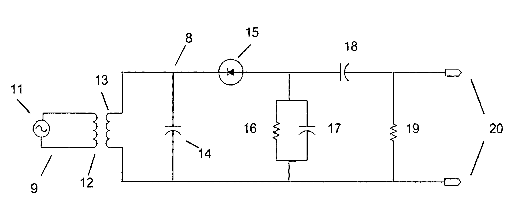
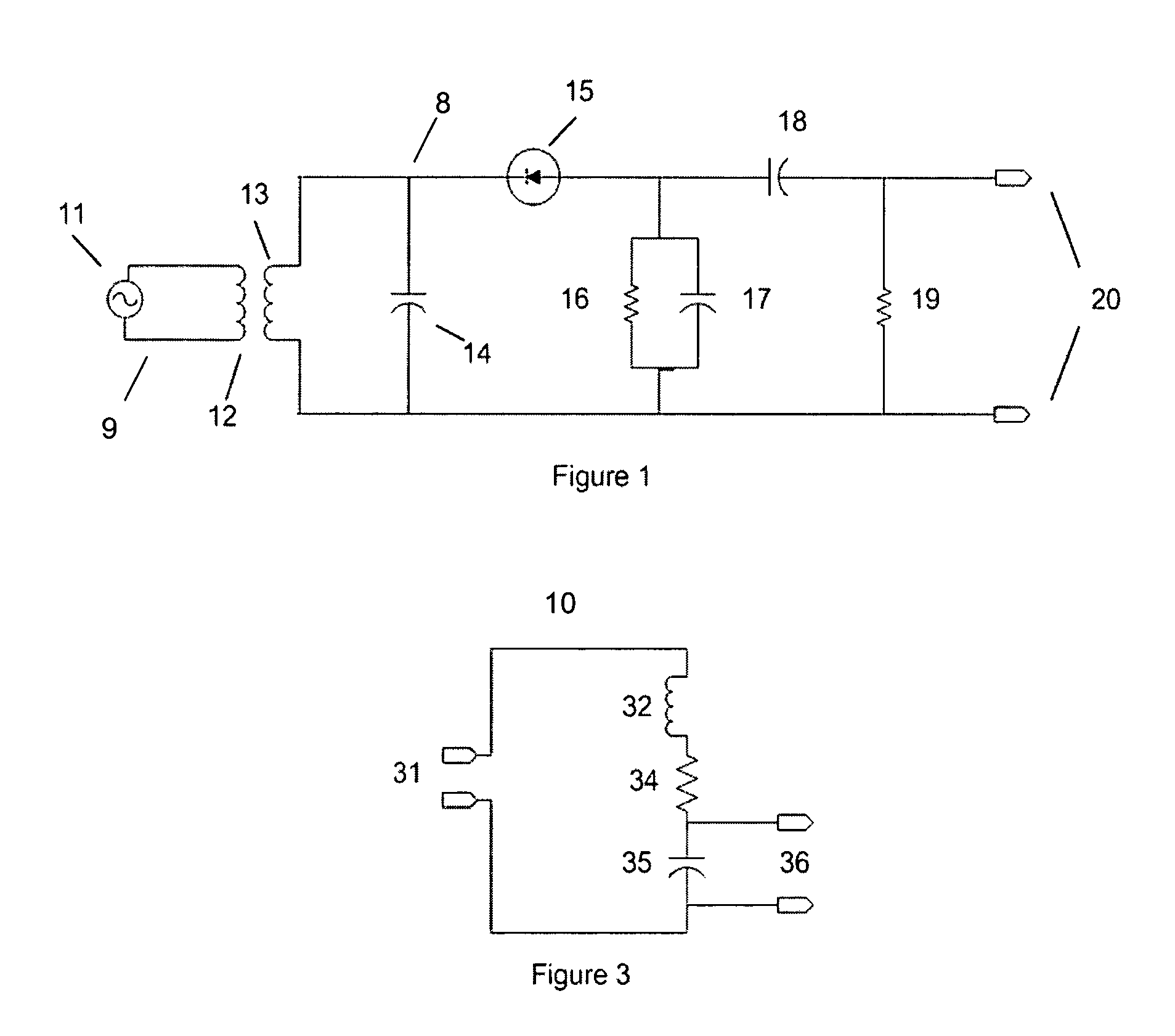
[0024]By reference from Communications Electronics Circuits second edition by J. J. DeFrance Rinehart Press, 1972, page 242 to FIG. 1, an exemplary description is made of a diode detector for the demodulation of electromagnetic waves. Means 9 for transmitting an electromagnetic signal includes an oscillator 11 and a loop antenna, depicted as an inductor 12. While the oscillator in this embodiment operates preferentially at 13.56 MHz, other frequencies may also be used. The tag 8 is attached to a surgical implement (not shown) and adapted to be inserted into a surgically exposed human body cavity includes means for receiving the transmitted electromagnetic signal and converting this electromagnetic signal into an electric signal. The means for receiving the electromagnetic signal is depicted as an inductor 13 which is also preferentially a wire loop antenna that is part of the body resonance detector circuit. The values of this inductor and its corresponding capacitor 14 are selected...


PUM


Abstract

A system and method for detecting a surgical implement retained within a surgically exposed human body cavity, includes a tag adapted to be attached to a surgical implement insertable within a human body cavity, including a means for receiving an electromagnetic signal and converting it into electric signal; and a means to impress said electric signal on the internal human (or an animal) body where said medical product is used; and means to transmit said electromagnetic signal; and a detecting means including reception means for receiving the electric signal from the body and a detector means connected to the reception means for detecting the electric signal. The envelope of the induced RF wave is demodulated, thus allowing the voltage at the output to vary at a significantly lower frequency. In the event such pulses are sensed, a sensory alert is actuated.

Description

[0001]This application claims the benefit of provisional Patent Application U.S. 60 / 685,048 applied May 25, 2005.BACKGROUND OF THE INVENTION[0002]This invention relates to detection of tagged objects and devices and particularly objects and devices utilized in body cavities during surgery and most particularly to surgical sponges which are frequently “lost” in such body cavities.[0003]During a surgical procedure, and especially in procedures where the chest or abdomen is open, foreign objects such as surgical sponges, needles and instruments are sometimes misplaced within the patient's body cavity. In general any foreign object left within the body can cause complications, (i.e. infection, pain, mental stress) even death, excepting objects such as clips and sutures that are purposely left as part of a surgical procedure.[0004]Presently there are two surgically acceptable procedures for detection and removal of the foreign objects. Firstly, a count of all objects used in the operatio...

Claims


Application Information

Patent Timeline
Patent Type & Authority Patents(United States)
IPC IPC(8): A61B3/16
CPCA61B5/06A61B19/44A61B2562/08A61B2019/448A61B5/062A61B90/90A61B90/98
Inventor BENSON, RANDALL JO'BRIEN, GEORGE PROYZEN, ZINOVY YSIEGEL, THOMAS S
Owner BENSON RANDALL J
Why Eureka
Try Eureka