High current power output stage

a high-current power output and power transistor technology, applied in the direction of dynamo-electric converter control, pulse technique, starter details, etc., can solve the problems of power loss and decrease of current-carrying capacity requirements of power transistors, and achieve high-current power output stages and low-cost power transistors. , good heat dissipation

Inactive Publication Date: 2010-04-13
CONTINENTAL AUTOMOTIVE GMBH
View PDF13 Cites 0 Cited by
  • Summary
  • Abstract
  • Description
  • Claims
  • Application Information

AI Technical Summary

Benefits of technology

[0008]An object of the present invention is to provide a high current power output stage which is protected against polarity reversal and which is simple and inexpensive.
[0011]By virtue of the fact that at least four power transistors are provided, through the diodes of which the current flows in the event of polarity reversal, the resulting power loss is distributed between the at least four power transistors. The requirements made of the current-carrying capacity of the power transistors decrease as a result. This has the advantage that inexpensive power transistors can be used. Furthermore, the protection of the high current power output stage against polarity reversal by the fusible link is simple and inexpensive. There is no need to provide any further components for the polarity-reversal protection. In particular, the requirement of a relay for interrupting the current flow in the event of polarity reversal is obviated. The high current power output stage is formed, e.g., as an H bridge with four power transistors or correspondingly has six power transistors for providing three-phase current. However, the high current power output stage can also have more than six power transistors.
[0012]In one embodiment of the invention, the at least four power transistors are disposed in each case as a semiconductor chip directly on a common carrier. At least one of the two electrical supply lines comprises at least one bonding wire. The advantage is that power transistors in the form of the semiconductor chips are particularly inexpensive and enable a particularly good heat dissipation. The current-carrying capacity of the electrical supply line in the region of the at least one bonding wire can be dimensioned in a very simple manner by the suitable choice of the thickness of the respective bonding wire or by the number of bonding wires. Furthermore, by virtue of the common carrier, the high current power output stage is compact and inexpensive in its production.
[0013]In a further embodiment of the invention, at least one additional diode is electrically connected in parallel with the at least four power transistors between the supply potential and the reference potential in such a way that it is turned off during normal operation of the high current power output stage and is in the on state when the supply potential and the reference potential are interchanged. This has the advantage that the resulting power loss through the current in the event of polarity reversal is also distributed to the at least one additional diode, such that the requirements made of the current-carrying capacity of the diodes of the at least four power transistors and of the at least one additional diode are reduced further. The power transistors and the at least one additional diode can thus be particularly inexpensive.

Problems solved by technology

By virtue of the fact that at least four power transistors are provided, through the diodes of which the current flows in the event of polarity reversal, the resulting power loss is distributed between the at least four power transistors.
The requirements made of the current-carrying capacity of the power transistors decrease as a result.

Method used


Image

  • High current power output stage
  • High current power output stage
  • High current power output stage

Examples


Embodiment Construction

[0018]Elements of identical construction or function are provided with the same reference symbols throughout the figures.

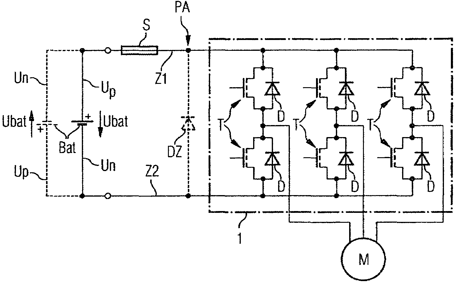
[0019]A circuit arrangement comprises a battery Bat, a high current power output stage PA and an electric motor M (FIG. 1). The high current power output stage PA is coupled via a first supply line Z1 to a supply potential Up and via a second supply line Z2 to a reference potential Un of the battery Bat. The battery Bat provides a battery voltage Ubat for operation of the high current power output stage. The high current power output stage PA is electrically coupled to the electric motor M. The electric motor M is operated by means of three-phase current and the high current power output stage PA is designed to generate the three phases of the three-phase current for operation of the electric motor M from the battery voltage Ubat.

[0020]The high current power output stage PA comprises, for each of the three phases of the three-phase current, in each case a series c...


PUM


Abstract

A high current end power stage comprises at least four power transistors, two electrical supply lines and a safety fuse. The at least four power transistors have each a diode which is blocked during normal operation of the respective power transistor. The two electrical supply lines couple the at least four power transistors with a supply potential and a reference potential such that two of the at least four power transistors are connected electrically between the supply potential and the reference potential. The safety fuse is connected in series to the at least four power transistors in at least one of the two electrical supply lines. The at least one safety fuse can be triggered by a current which flows through the diode of the at least four power transistors, said diode being then arranged in the direction of conduction, when the supply potential and reference potential are exchanged.

Description

CROSS REFERENCE TO RELATED APPLICATIONS[0001]This is a U.S. national stage of application No. PCT / EP2006 / 066590, filed on 21 Sep. 2006. Priority is claimed on the following German Application No. 10 2005 046 682.6, filed 29 Sep. 2005 the content of which is incorporated here by reference.BACKGROUND OF THE INVENTION[0002]1. Field of the Invention[0003]The invention relates to a high current power output stage comprising power transistors, in particular MOSFET power transistors.[0004]2. Description of the Prior Art[0005]High current power output stages are used, for example, in control units of motor vehicles for driving electric motors, e.g., for an electric power steering device or an electric brake force amplifier device. The high current power output stage is operated in a normal operation mode, e.g., with currents of the order of magnitude of 100 amperes. The electrical energy required is provided by a generator device or a battery. When the battery is replaced, the battery can i...

Claims


Application Information

Patent Timeline
Patent Type & Authority Patents(United States)
IPC IPC(8): H03K17/56
CPCH02H11/002H02H7/0838H02H11/00H03K3/53
Inventor VEIT, CLAUDIUSWEISS, WERNER
Owner CONTINENTAL AUTOMOTIVE GMBH
Why Eureka
Try Eureka