Packet sniffer node and system including the same to assess wireless communication performance

a wireless communication and packet sniffer technology, applied in the field of wireless communication performance assessment systems, can solve problems such as changing the interfering signal strength, unable to reproduce field conditions in the lab, and unable to reproduce low-power wireless systems that function correctly at the present tim

Inactive Publication Date: 2010-04-13
EATON CORP
View PDF4 Cites 19 Cited by
  • Summary
  • Abstract
  • Description
  • Claims
  • Application Information

AI Technical Summary

Problems solved by technology

When factors like node hardware platform and EMI generation by existing operational equipment are taken into account, it is simply not possible to reproduce field conditions in the lab.
Environmental effects that impact correct operation include, for example, path loss, multi-path fading, shadowing, interference and jamming.
These environmental effects vary over time, such that a low-power wireless system that functions correctly at the present time may not function correctly in the future.
Similarly, a piece of equipment turned on or uncovered can change the interfering signal strength.
However, it is often cumbersome and unsafe to route wires in an existing commercial or industrial environment.
For example, an artificial ground plane, such as is created by the control, data or power wiring of known prior systems, can distort the measurements and lead to a false assessment of communication performance.
Direct measurement of the RF environment has several disadvantages: (1) the effort is intensive (trained personnel are required with generally several person-hours of effort per hour of measurement); (2) it is difficult to test many points for many hours; (3) wireless communication performance must be inferred (it is not directly measured); (4) test instruments are relatively expensive (many times more expensive than communication nodes); and (5) test instruments incorporate radios and antennas different from those used in deployed wireless devices.
If it is not difficult to install the communicating nodes, then the manpower requirement may be slight.
However, operating a communication network to measure communication characteristics has two significant disadvantages.
Second, the Network layer protocol introduces bias into the measurements.
If many data-carrying packets are lost, then the network will have low data capacity, which is part of the desired measurement.
However, if too many control packets are lost, then the network will cease to function (it is said to collapse).
Thus, layer 1 tests can operate under very general circumstances, but are effort intensive and limited in other ways.
Known packet sniffers, which dump raw packet data, are not designed for wireless link assessment.

Method used


Image

  • Packet sniffer node and system including the same to assess wireless communication performance
  • Packet sniffer node and system including the same to assess wireless communication performance
  • Packet sniffer node and system including the same to assess wireless communication performance

Examples


example 1

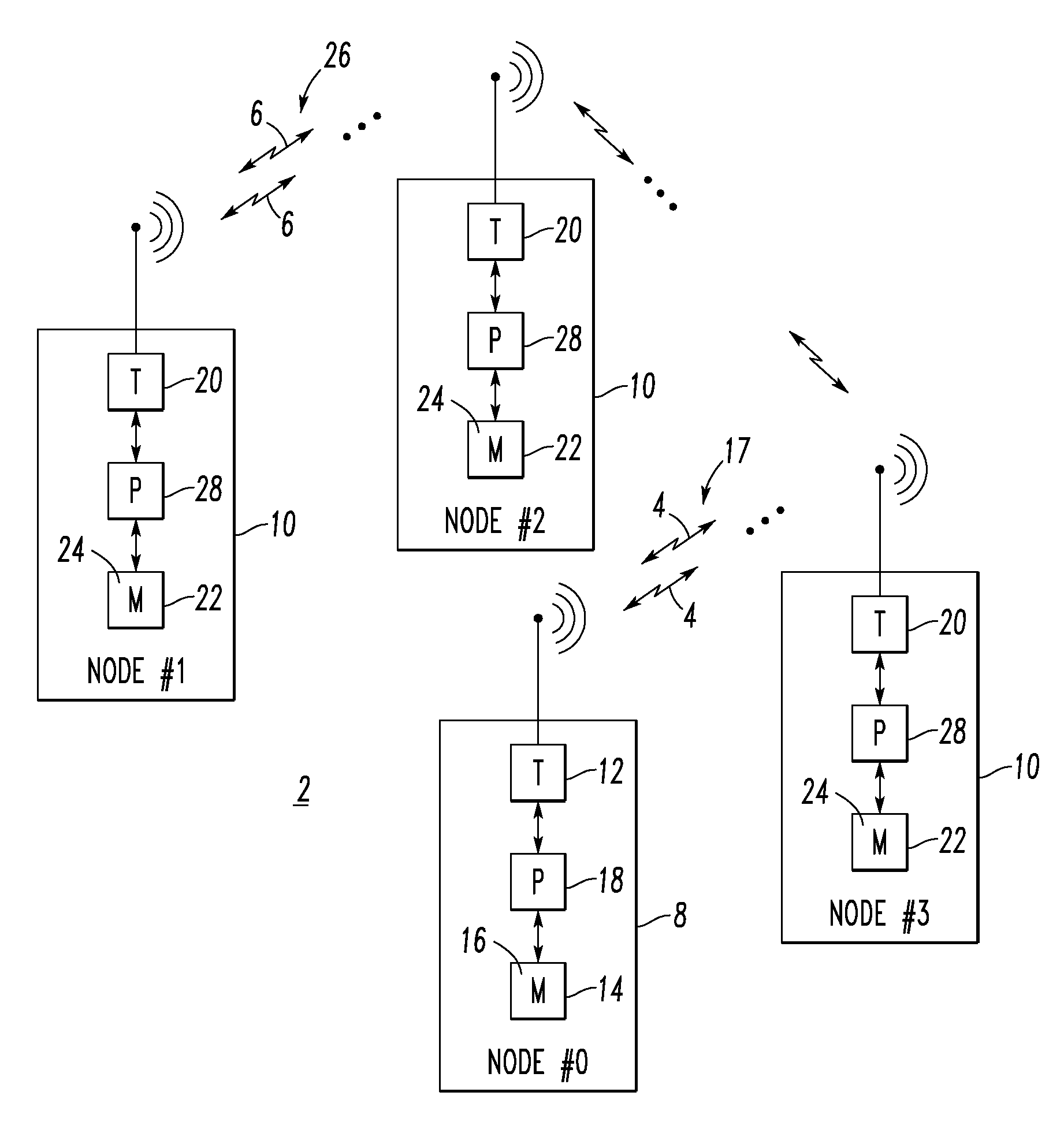
[0076]The disclosed system 2 measures wireless performance and can be used, for example, for wireless network site surveys. The system 2, which is a layer-two test, significantly reduces the cost and increases the information yield of site surveys.

example 2

[0077]The system 2 is truly wireless and there is no wired data connection for experiment control and no wired power connection. The system nodes 8,10 operate without any wiring, in order that the nodes can be placed in active industrial settings where wiring is impractical or impossible. Hence, no artificial ground plane is formed among the test nodes 8,10 that could otherwise distort the measurements and lead to a false assessment of communication performance. Furthermore, the system 2 has a relatively very simple operation: (1) place the nodes 8,10 as desired; (2) install the pre-programmed memory 14,22 (e.g., without limitation, compact flash cards); and (3) turn on the nodes 8,10. This operation makes the system 2 attractive for industrial testing.

example 3

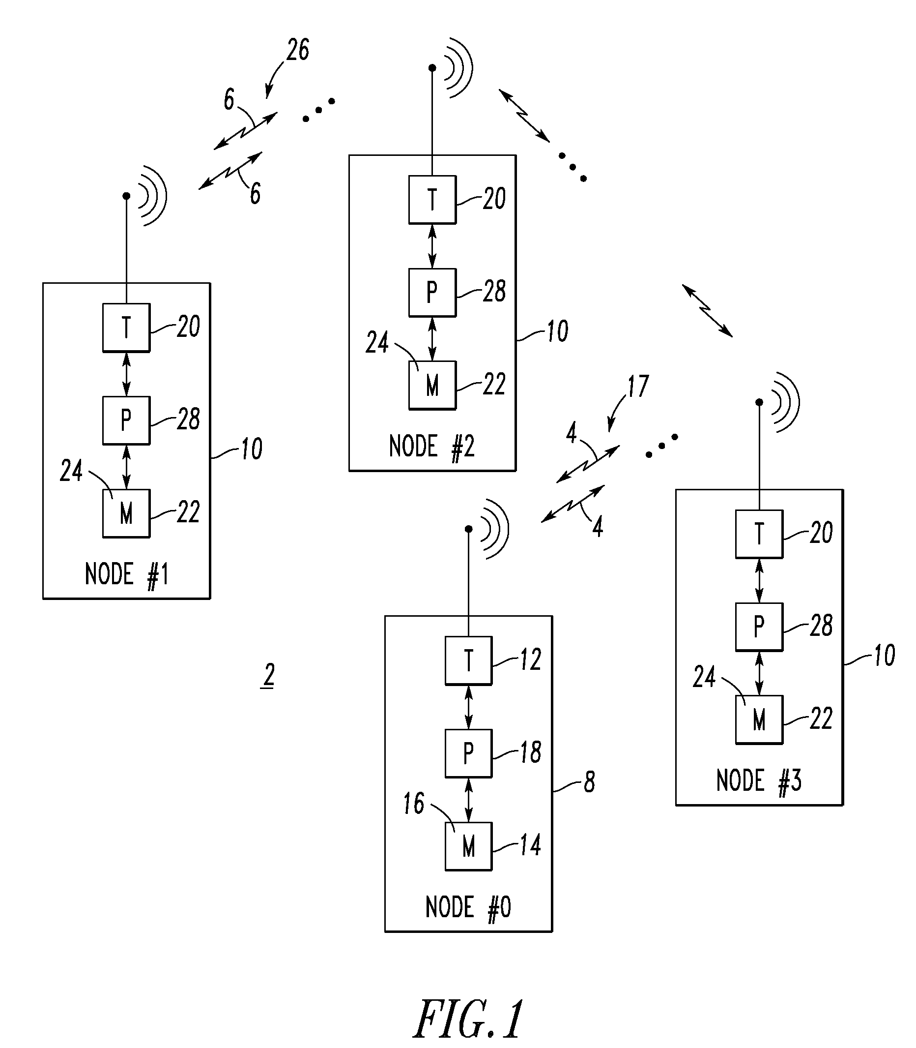
[0078]As shown in FIG. 2, each system node 30 of the system 2 (FIG. 1) has a single user input 32 (e.g., button; on / off switch) and it does not matter in what order the nodes are turned on. All configuration information for a test is stored in removable media (e.g., without limitation, a compact flash card 34). The system nodes, such as 30, synchronize and execute the test automatically. If a node is shut down during the test (e.g., to exchange a battery 36 or compact flash card 34; by accident), then when it is turned back on it will automatically rejoin the test. If any node, other than the “master node”8 (node #0 of FIG. 1) is turned off or disabled, the test continues with no change other than the loss of transmitted packets from the disabled node. The corresponding schedule 16,24 may be transferred from the compact flash card 34 to the memory 14,22 of the corresponding node 8,10.

[0079]The system nodes 8,10,30 of FIGS. 1 and 2 can make successful measurements even when the packe...


PUM


Abstract

A wireless system includes a plurality of wireless nodes structured to participate in a system test of the wireless nodes. The system test includes a plurality of test packets. A packet sniffer node includes a wireless receiver, a memory storing a schedule defining transmission and reception of the test packets by the wireless nodes, and a processor cooperating with the wireless receiver and the memory to receive at least some of the test packets responsive to the schedule, and to output data corresponding to the received test packets of the system test. A monitoring computer receives the output data from the processor of the packet sniffer node. Operation of the packet sniffer node, which does not transmit, does interfere with or alter execution of the system test.

Description

[0001]This invention was made with Government support under DOE Cooperative Agreement No. DE-FC26-04NT42071 awarded by DOE. The Government has certain rights in this invention.CROSS-REFERENCE TO RELATED APPLICATIONS[0002]This application is related to commonly assigned, concurrently filed:[0003]U.S. patent application Ser. No. 11 / 613,337, filed Dec. 20, 2006, entitled “System And Method For Assessment Of Wireless Communication Performance”;[0004]U.S. patent application Ser. No. 11 / 613,300, filed Dec. 20, 2006, entitled “System And Method Employing Wireless Communications And Predetermined Measurement Functions Of Wireless Nodes For Assessing Wireless Communication Performance”; and[0005]U.S. patent application Ser. No. 11 / 613,406, filed Dec. 20, 2006, entitled “Synchronization System And Method For Wireless Communicating Nodes”.BACKGROUND OF THE INVENTION[0006]1. Field of the Invention[0007]This invention pertains generally to wireless systems and, more particularly, to systems for ...

Claims


Application Information

Patent Timeline
Patent Type & Authority Patents(United States)
IPC IPC(8): H04W4/00G01R31/08G06F11/00G08C15/00H04B17/00H04J1/16H04J3/14H04L1/00H04L12/26H04W24/00
CPCH04W24/08H04L43/18H04L63/1425
Inventor ARMSTRONG, BRIAN S. R.PEREIRA, LUIS R.DAS, SUJIT R.RENTEL, CARLOS H.
Owner EATON CORP
Why Eureka
Try Eureka