
Powered air-purifying respirator system

a respirator and air purification technology, applied in the direction of respirators, valve operating means/release devices, instruments, etc., can solve the problems of increasing the physical size of resistors needed to limit the power flow, reducing the speed of the motor and volume, and creating an explosive atmosphere of dust and gases. , to achieve the effect of high current/power level and high current level

Inactive Publication Date: 2010-04-20
E D BULLARD
View PDF19 Cites 16 Cited by
  • Summary
  • Abstract
  • Description
  • Claims
  • Application Information

AI Technical Summary

Benefits of technology

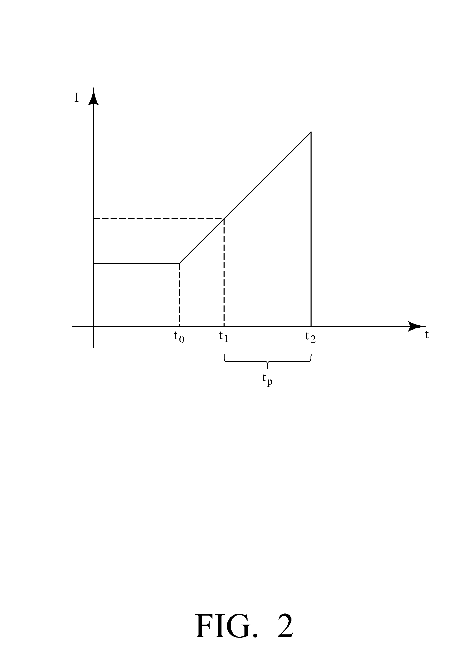
[0013]The invention also provides sufficient power to properly start and operate a blower of a PAPR. Blower motors starting from a stopped state require relatively high current/power levels to initiate spinning and to spin up to operating speed. This relatively high current level will cause a trip e

Problems solved by technology

However, dusts and gases often create an explosive atmosphere, in addition to the respiratory issues described above.
However, while the resistor circuit does provide a solution for making PAPRs safe, several problems exist with the use of such circuits.
Further, the resistor circuit drops the voltage available to the blower motor, which for a DC motor will decrease the speed of the motor and the volume of air forced through the air-purifying element to the headpiece.
Such batteries are larger and have a larger amp-hour capacity, also increasing the physical size of the resistors needed to limit the power flow.
The increased size of the resistors poses problems for designers that wish to combine the battery and the resistor circuits in a single battery unit or “battery pack.” Even further yet, increases in the power capacity of the batteries and the size of the resistors also results in increased heat that must be dissipated by the battery and the battery pack during a short circuit event, which also poses additional design challenges.

Method used


Image

  • Powered air-purifying respirator system
  • Powered air-purifying respirator system
  • Powered air-purifying respirator system

Examples


Embodiment Construction

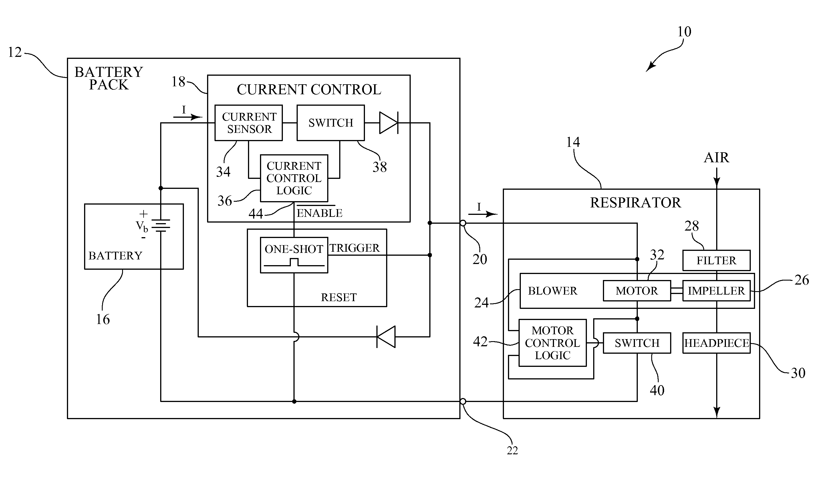
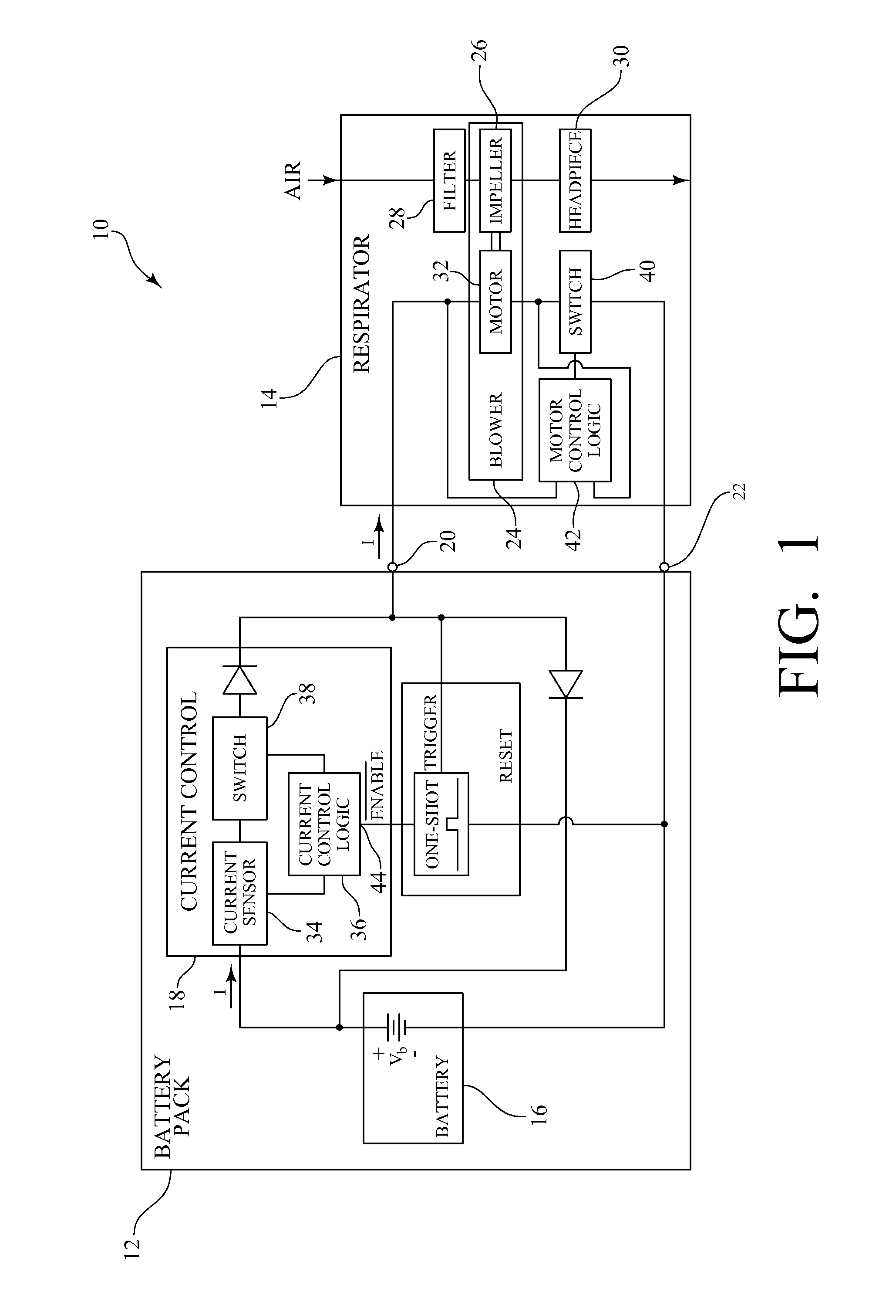
[0022]As shown in FIG. 1, an exemplary powered air-purifying respirator system 10 includes a battery pack 12 and a respirator unit 14. The battery pack 12 has a battery 16, a current control means 18, a positive battery pack terminal 20 and a negative battery pack terminal 22. The respirator unit 14 has a blower 24. The blower 24 includes an impeller 26 for pulling air through a filter 28 and pushing the filtered air to a headpiece 30, and a motor 32 in electrical communication with the battery 16 for driving the impeller 26. The current control means 18 is for sensing the current flow, I, from the battery 16 to the motor 32 and stopping the current flow when it exceeds a threshold value, Ithresh, for a predetermined amount of time, tp. One of skill in the art will recognize that the current flow is directly proportional to power flow in this DC circuit, since it is assumed that the voltage of the battery is substantially constant. Thus, the current flow, I, has a corresponding powe...


PUM


Abstract

Disclosed is an apparatus and method for operating powered air-purifying respirators safely in explosive atmospheres. The apparatus and method utilize a current control means for sensing a current flow from a battery to a motor, and stopping the current flow when the current flow exceeds a threshold value for a predetermined amount of time. Upon sensing that the current flow has exceeded the threshold value for the predetermined amount of time, the current control means immediately stops the current flow. The apparatus and method provides sufficient power to properly start and operate the motor by providing a soft start to the motor by limiting the duration of higher than threshold operating current to intervals shorter than the predetermined amount of time. Pulse width modulation is used to ramp-up the motor to speed by supplying pulses of energy to the motor that will not cause the current control means to stop the current flow.

Description

CROSS-REFERENCE TO RELATED APPLICATIONS[0001]Not applicable.STATEMENT REGARDING FEDERALLY SPONSORED RESEARCH OR DEVELOPMENT[0002]Not applicable.REFERENCE TO A “SEQUENTIAL LISTING,” A TABLE, OR A COMPUTER PROGRAM LISTING APPENDIX SUBMITTED ON A COMPACT DISC[0003]Not applicable.BACKGROUND OF THE INVENTION[0004]1. Field of the Invention[0005]The present invention relates to powered air-purifying respirators (PAPRs). More particularly, the invention relates making PAPRs safe for use in explosive atmospheres.[0006]2. Description of Prior Art[0007]Air purifying respirators have an air-purifying filter, cartridge, or canister that removes specific air contaminants by passing ambient air through the air-purifying element. Powered air-purifying respirators (PAPRs) are air-purifying respirators that use a battery (preferably a rechargeable battery) to supply power to a blower to force ambient air through an air-purifying element to a headpiece. The headpiece forms a protective barrier between...

Claims


Application Information

Patent Timeline
IPC IPC(8): F16K31/02
CPCA62B18/006A62B7/10
Inventor JOHNSON, DOUGLAS V.JOHNSON, SHAUN D.
Owner E D BULLARD
Learn More