Method, apparatus, and kit for thermal suture cutting

a technology of thermal suture and suture blade, which is applied in the field of suture removal, can solve the problems of increasing patient discomfort, affecting patient comfort, and affecting patient comfort, so as to minimize patient discomfort, tissue disruption and bleeding, and less suture tension

Inactive Publication Date: 2010-04-20
BOVIE MEDICAL CORP
View PDF20 Cites 1196 Cited by
  • Summary
  • Abstract
  • Description
  • Claims
  • Application Information

AI Technical Summary

Benefits of technology

[0009]The present invention provides a method, instrument, and kit for applying heat to the loop portion of a suture used to close a wound so as to melt the suture material, causing the loop to rupture. The cutting method disclosed and associated instrument allow the suture to be separated while producing less tension in the suture than current methods, thereby minimizing patient discomfort, tissue disruption and bleeding.
[0022]The circuitry ensures the heating of a heating element to a predetermined temperature suitable for thermally rupturing suture materials when the heating element resistance and source voltage fall within predetermined ranges. The circuit may be a timer circuit which connects power from the source to the heating element for a predetermined period of time. In a preferred embodiment, the circuit supplies a predetermined amount of electrical energy to the heating element such that the element reaches a predetermined temperature, the circuit having a means for modifying its output based on the resistance of the element so as to achieve the predetermined energy value. In a preferred embodiment, the circuitry also has a timing means which prevents a second activation until a predetermined time has elapsed following a first activation so as to thereby prevent heating of the conductive member distal tip to temperatures which could potentially burn a patient.
[0027]In a preferred embodiment, the first conductive member is longer than the second conductive member and has a tapered distal end. Both the conductive members are preferably formed from an easily machined metallic material, such as brass or stainless steel, and should have good thermal conduction properties. Both the members have a coplanar axis with each other and with the proximal handle portion. The distal end of the second element is connected to the tapered distal end of the first elongated member by a thin resistive heating element. The thin resistive heating element forms an acute angle of about 5 to 40 degrees with the adjacent surface of the first elongated member. The first and second conductive members are connected to the power source and the activation button by a suitable conduction means discussed above. Because the conductive members have much larger cross-sections than the thin resistive heating element, the conductive members are not heated by the current. Because the element is energized for only a short period of time, heating of the conductive members by the filament is minimal.

Problems solved by technology

However, they carry with them the additional task of requiring manual suture removal.
The removal of sutures is problematic for many doctors.
This technique requires considerable tension on, and manipulation of, the stitch.
The resulting pain, bleeding, and tissue disruption are uncomfortable and anxiety provoking for the patient and compromise the cosmesis of the wound repair.
Lastly, the technique is time consuming for the physician.
Unfortunately, the scissors generally have a blunt end, making it difficult to raise the stitch sufficiently off the skin to slip the distal tip of the scissors under the stitch.
Additionally, the action of bringing the scissors blades together to cut the stitch creates significant tension on the suture.
The second current method for suture removal replaces the scissors with a thin knife but requires the same manipulation and results in similar tissue disruption and bleeding.

Method used


Image

  • Method, apparatus, and kit for thermal suture cutting
  • Method, apparatus, and kit for thermal suture cutting
  • Method, apparatus, and kit for thermal suture cutting

Examples


Embodiment Construction

[0080]In the context of the present invention, the following definitions apply:

[0081]The term “suture” is used to refer both to the fine thread or other material used surgically to close a wound or join tissues and to the stitch so formed.

[0082]The term “distal” refers to that end or portion which is situated farthest from the hand of the operator and closest to the body of the patient when the device is in use.

[0083]The term “proximal” refers to that end or portion situated closest to the hand of the operator and farthest away from the body of the patient when the device is in use.

[0084]The accompanying figures, described in detail below, illustrate aspects of the invention but are in no way intended to limit the scope of the present invention.

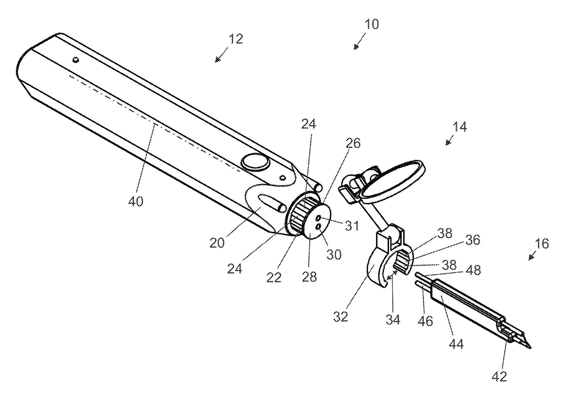
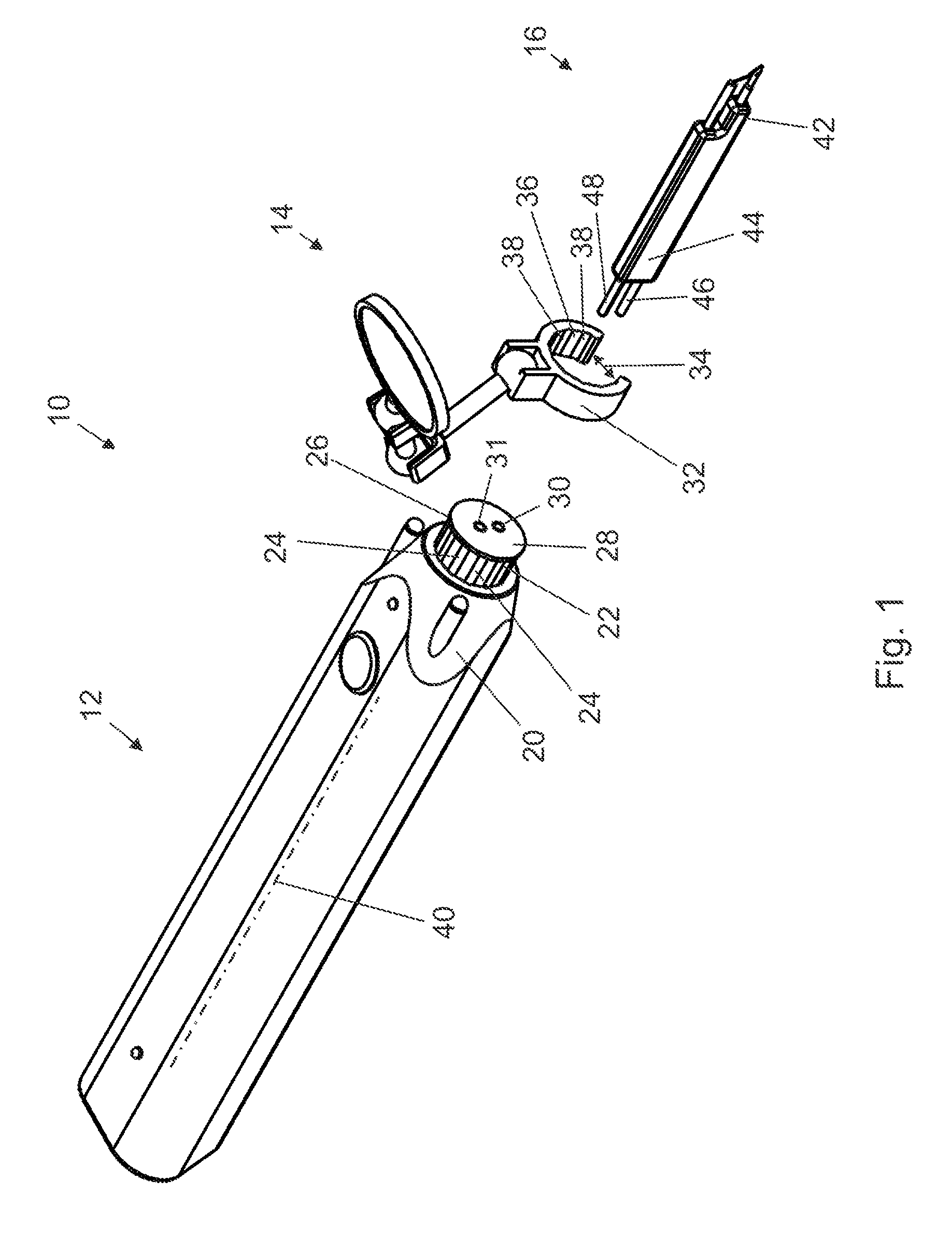
[0085]Referring to the figures showing a suture cutter 10 constructed in accordance with the principles of this invention, FIG. 1 depicts an exploded view of suture cutter 10, cutter 10 having a first, proximal assembly 12 forming a handle, a...


PUM


Abstract

A novel suture removal instrument, kit and technique are described herein. The invention utilizes a newly designed thermal filament to allow the tip of the suture removal instrument to be slipped under the stitch in order to heat and cut the stitch. Current suture removal techniques utilize scissors, forceps, and / or scalpels. These techniques, which are well known in the art, are problematic because they exert tension on the stitch and are associated with patient discomfort. Small stitches add to the difficulty of suture removal because they have less suture laxity for scissor insertion. The present invention therefore allows for more rapid suture removal with less patient discomfort and at a competitive or lower cost.

Description

PRIORITY INFORMATION[0001]This application is a continuation-in-part of U.S. patent application Ser. No. 11 / 124,288, filed May 9, 2005, now abandoned, which, in turn, is a continuation-in-part of U.S. patent application Ser. No. 10 / 600,368 filed Jun. 23, 2003, now U.S. Pat. No. 7,048,746, which, in turn, claims the benefit of U.S. Provisional Application Ser. No. 60 / 391,887, filed Jun. 27, 2002. The contents of these applications are hereby incorporated by reference herein in their entirety.TECHNICAL FIELD OF THE INVENTION[0002]The present invention relates to the field of suture removal. More particularly, the present invention provides a method, instrument, and kit for thermally cutting a suture, which minimizes the tension placed on the suture during removal, thereby reducing pain, bleeding and tissue disruption.BACKGROUND OF THE INVENTION[0003]Suture removal is an important part of wound repair in medicine. Internal sutures are absorbable so they are essentially “removed” by the...

Claims


Application Information

Patent Timeline
Patent Type & Authority Patents(United States)
IPC IPC(8): A61B17/10A61B17/04A61B17/06A61B18/08
CPCA61B17/0467A61B2019/521A61B2017/0619A61B19/26A61B2017/00154A61B2017/00084A61B18/08A61B2017/00194A61B2017/00123A61B2017/00734A61B2017/0046A61B2090/309A61B90/50
Inventor VAN WYK, ROBERT A.ROLNICK, MICHAEL A.WARDEN, MATTHEW P.SIMEONOV, BORISLAV S.BARON, FRED
Owner BOVIE MEDICAL CORP
Why Eureka
Try Eureka