Envelope modulator saturation detection using a DC-DC converter

Active Publication Date: 2010-04-20
III HLDG 12 LLC
View PDF23 Cites 64 Cited by
  • Summary
  • Abstract
  • Description
  • Claims
  • Application Information

AI Technical Summary

Benefits of technology

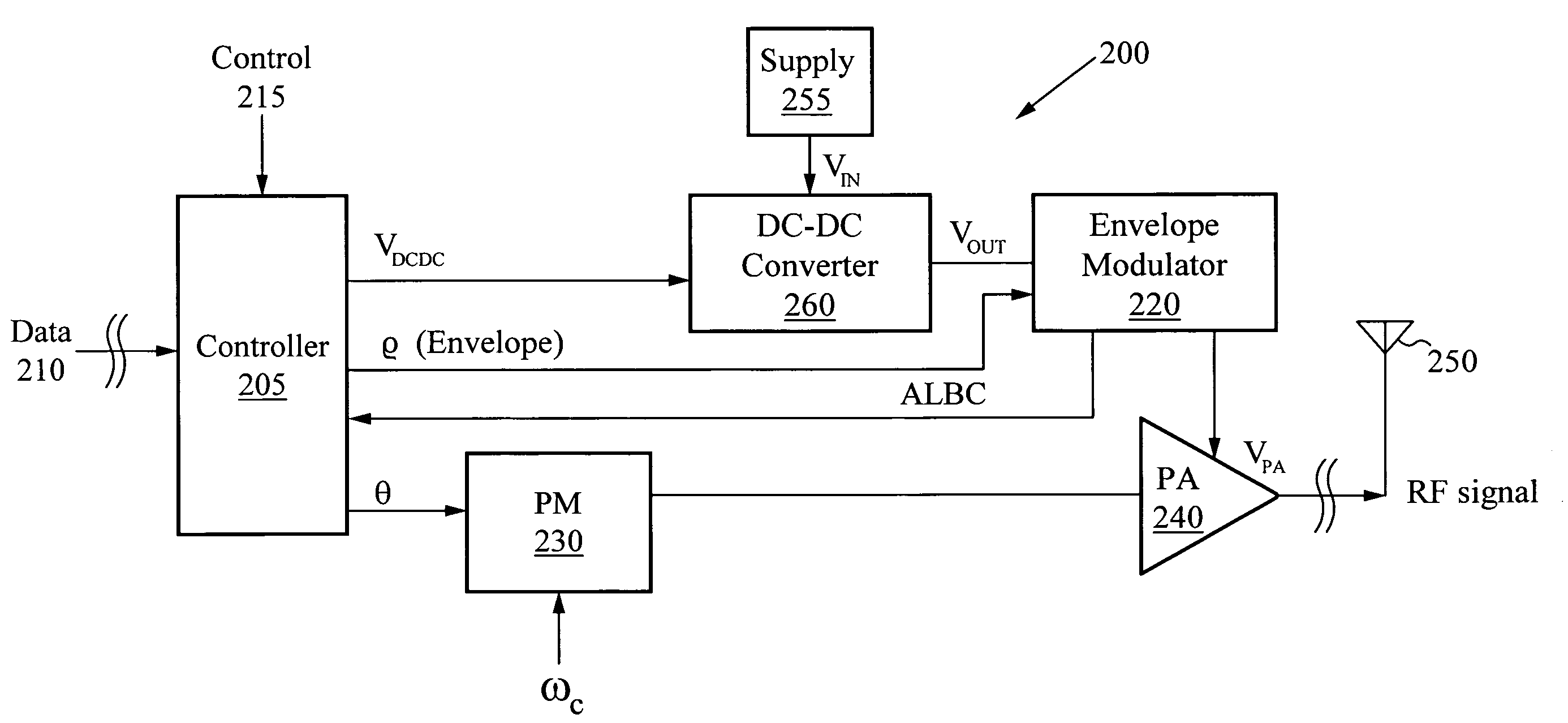
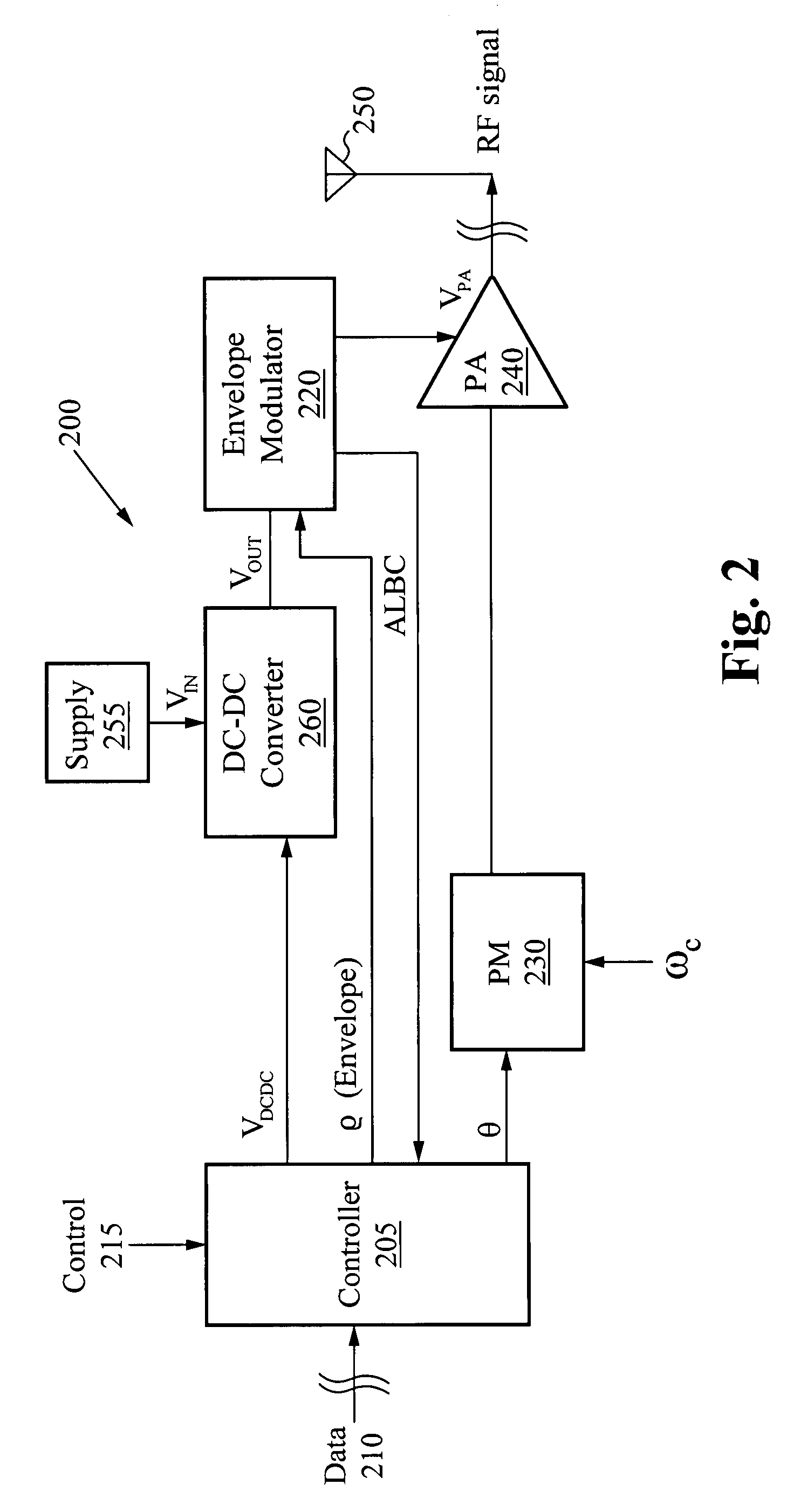
[0008]The voltage input preferably indicates a low battery condition, and the feedback signal indicates when the voltage input comprises a low signal. In these embodiments, the polar signal

Problems solved by technology

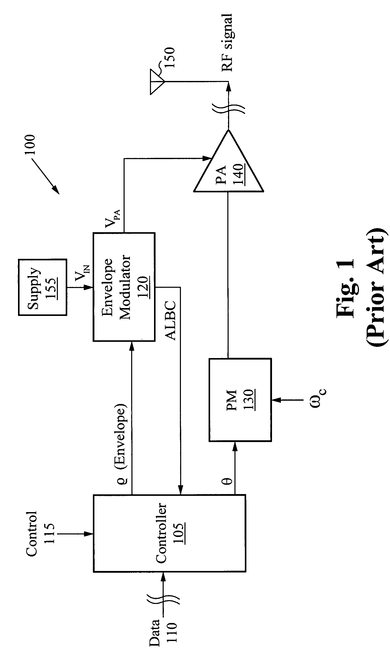
However, polar implementations have drawbacks as well.
Hence, if the supply power is low, such as in low battery situations, for example, then distortion will occur for high envelope power peaks.
Moreover, the power amplifier of the envelope modulation circuitry tends to operate in an inefficient ran

Method used


Image

  • Envelope modulator saturation detection using a DC-DC converter
  • Envelope modulator saturation detection using a DC-DC converter
  • Envelope modulator saturation detection using a DC-DC converter

Examples


Embodiment Construction

[0015]Embodiments of the present application are described herein in the context of an apparatus and method for efficient envelope modulation. Those of ordinary skill in the art will realize that the following detailed description of the present application is illustrative only and is not intended to be in any way limiting. Other embodiments of the present application will readily suggest themselves to such skilled persons having the benefit of this disclosure.

[0016]Reference will now be made in detail to implementations of the present application as illustrated in the accompanying drawings. The same reference indicators will be used throughout the drawings and the following detailed description to refer to the same or like parts. In the interest of clarity, not all of the routine features of the implementations described herein are shown and described. It will, of course, be appreciated that in the development of any such actual implementation, numerous implementation-specific deci...


PUM


Abstract

In an embodiment of the invention, a system provides for efficient polar and linear signal modulation. The system has a controller coupled to a voltage converter and a modulator. The system also has an amplifier coupled to the voltage converter and the phase modulator. The controller is for receiving an input and providing a polar signal. The voltage converter is for receiving the polar signal, receiving a voltage input, and providing a power signal. The amplifier is for amplifying the modulated signal based on the power signal. The voltage converter provides a feedback signal to the controller, and the controller adjusts a scale of modulation, such as a peak of the modulation signal, based on the feedback signal, such that the output power and the amplification by the amplifier are based on the feedback signal.

Description

FIELD OF THE INVENTION[0001]The present invention relates to the field of modulators. More specifically the present invention relates to efficient modulation.BACKGROUND[0002]In recent years, researchers have proposed and implemented so called “polar” architectures for the improved transmission of signals. These polar architectures, rather than using complex In-phase Quadrature (IQ) components of a data signal, operate by using the polar components of the data signal. Accordingly, polar implementations of modulation circuitry are used to transmit and receive voice and / or data in the radio frequency (RF) bands of the communications spectrum. Polar implementations have a number of advantages over their IQ counterparts.[0003]However, polar implementations have drawbacks as well. For instance, polar envelope modulation (EM) circuitry typically has no direct visibility of the supply voltage on the envelope modulation driver. Hence, if the supply power is low, such as in low battery situat...

Claims


Application Information

Patent Timeline
IPC IPC(8): H04B1/04
CPCH03C5/00H03C1/06
Inventor MCCUNE, EARL W.
Owner III HLDG 12 LLC
Why Eureka
Try Eureka