
Transmission power control method and mobile terminal apparatus

a technology of transmission power control and mobile terminal, applied in the direction of transmission monitoring, frequency-division multiplex, instruments, etc., can solve the problems of inability to continuously execute data packet transmission, inability to transmit signals, and inability to maintain uplink transmission power control, so as to prevent the occurrence of interference due to excessive power, the probability of correct reception of data packets, and the effect of effective utilization of radio intervals

Inactive Publication Date: 2010-04-20
FUJITSU LTD
View PDF15 Cites 6 Cited by
  • Summary
  • Abstract
  • Description
  • Claims
  • Application Information

AI Technical Summary

Benefits of technology

The invention relates to a method for controlling the transmission power of uplink data packets in a radio communication system. The technical effect of the invention is to enable resumption of transmission of uplink data packets at an appropriate transmission power even when TPC commands are not received during interruption of uplink data packet transmission. This method allows for effective utilization of radio intervals and prevents interference due to excessive power. Additionally, the invention takes into account the movement speed of the mobile terminal and adjusts the number of time slots for calculating the moving average accordingly.

Problems solved by technology

However, in a fourth-generation mobile communication system and other radio packet transmission systems, data packet transmission may not be executed continuously.
But in the above fourth-generation mobile communication system, the pilot signals may not be transmitted during transmission interruption periods.
Consequently during transmission interruption periods when uplink packet transmission is not performed, uplink transmission power control is no longer continuous, and the problem arises that transmission power values may be inappropriate at the time of resumption of data packet transmission.
However, this method has the problem that efficient utilization of the radio interval is not possible.
However, there is the possibility that the power value may deviate greatly from the value actually required.
In this case, if the transmission power value stipulated by specifications is smaller than the value actually required, there arises the possibility that at the time of resumption of data packet transmission, transmitted data packets cannot be properly received and decoded by the base station; conversely, if the value is larger than the value actually required, the possibility that the base station will succeed in reception and decoding is increased, but increased occurrence of interference due to excessive power becomes a problem.
However, in this Prior Art Method 1, the transmission power at the time of transmission resumption is not determined taking into account the communication states at the time of the start of transmission interruption and at the time of transmission resumption, and so the problem occurs that transmission is not performed at an appropriate transmission power when transmission is resumed.
However, this method assumes that the transmission interruption period is short (for example, 5 to 6 ms or less), and uses the transmission powers or transmission power command values for fixed intervals immediately preceding transmission interruption, and so there is the problem that at the time of transmission resumption, transmission at an appropriate transmission power is not possible.

Method used


Image

  • Transmission power control method and mobile terminal apparatus
  • Transmission power control method and mobile terminal apparatus
  • Transmission power control method and mobile terminal apparatus

Examples


first embodiment

(A) First Embodiment

(a) Configuration

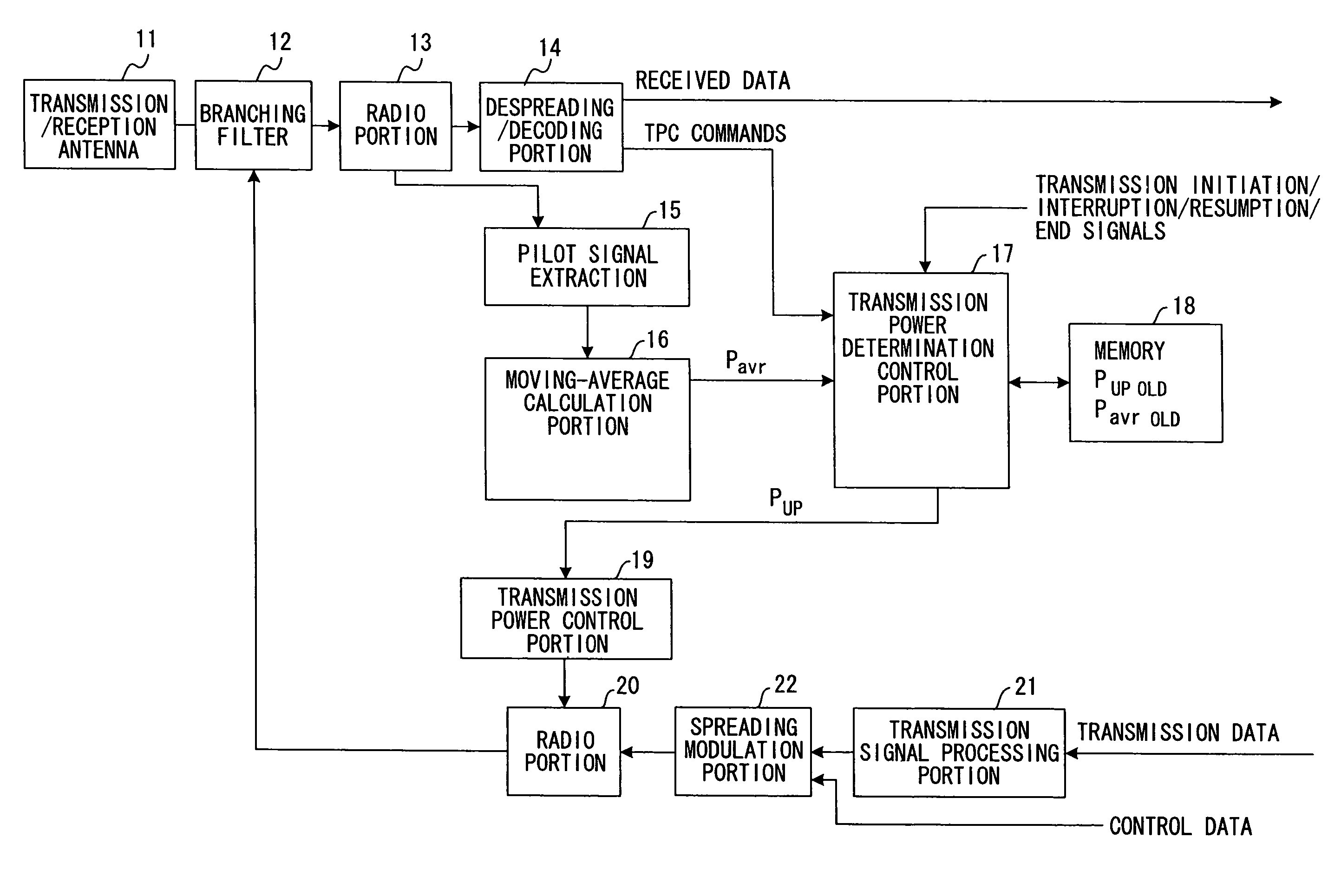
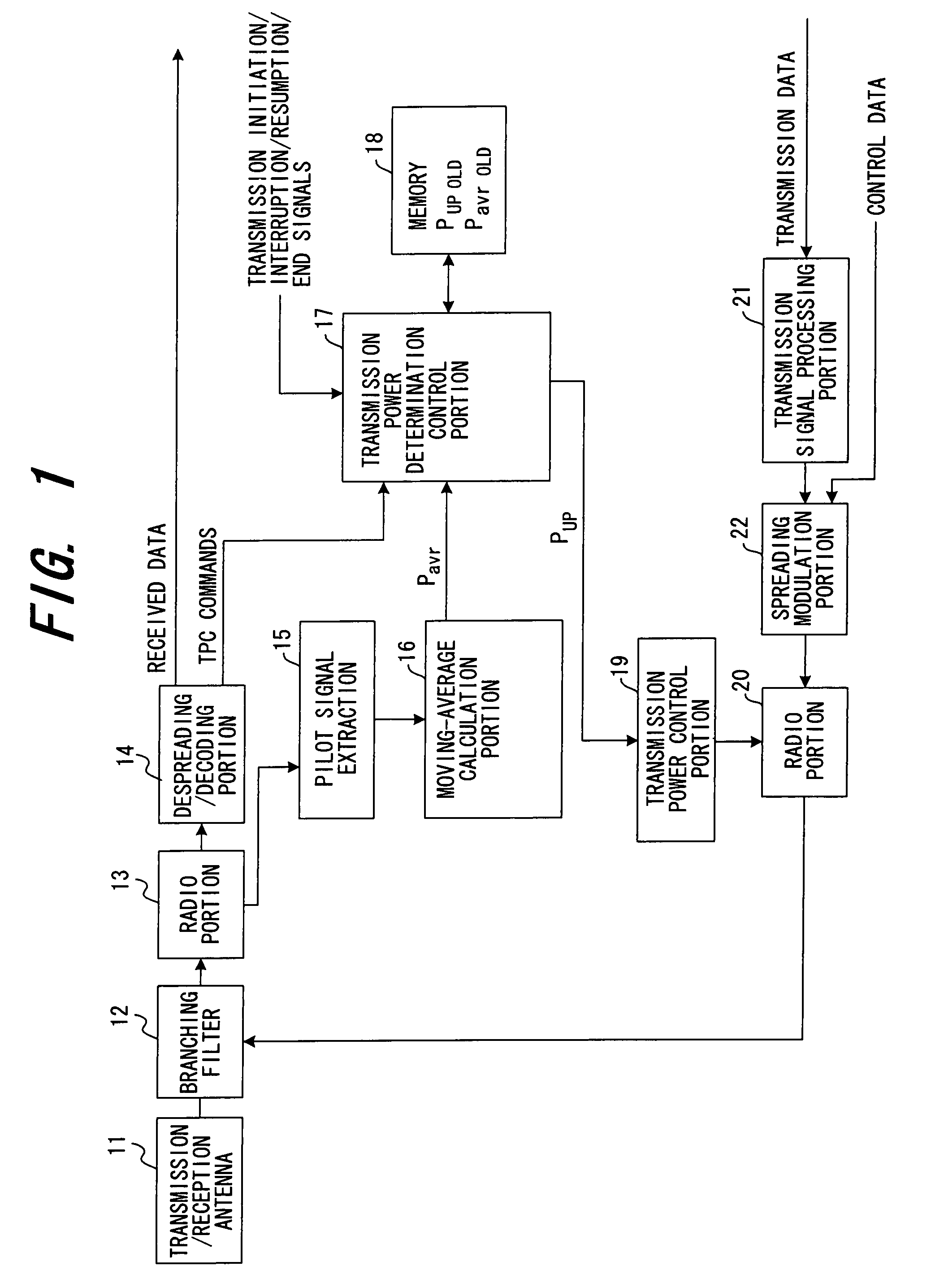
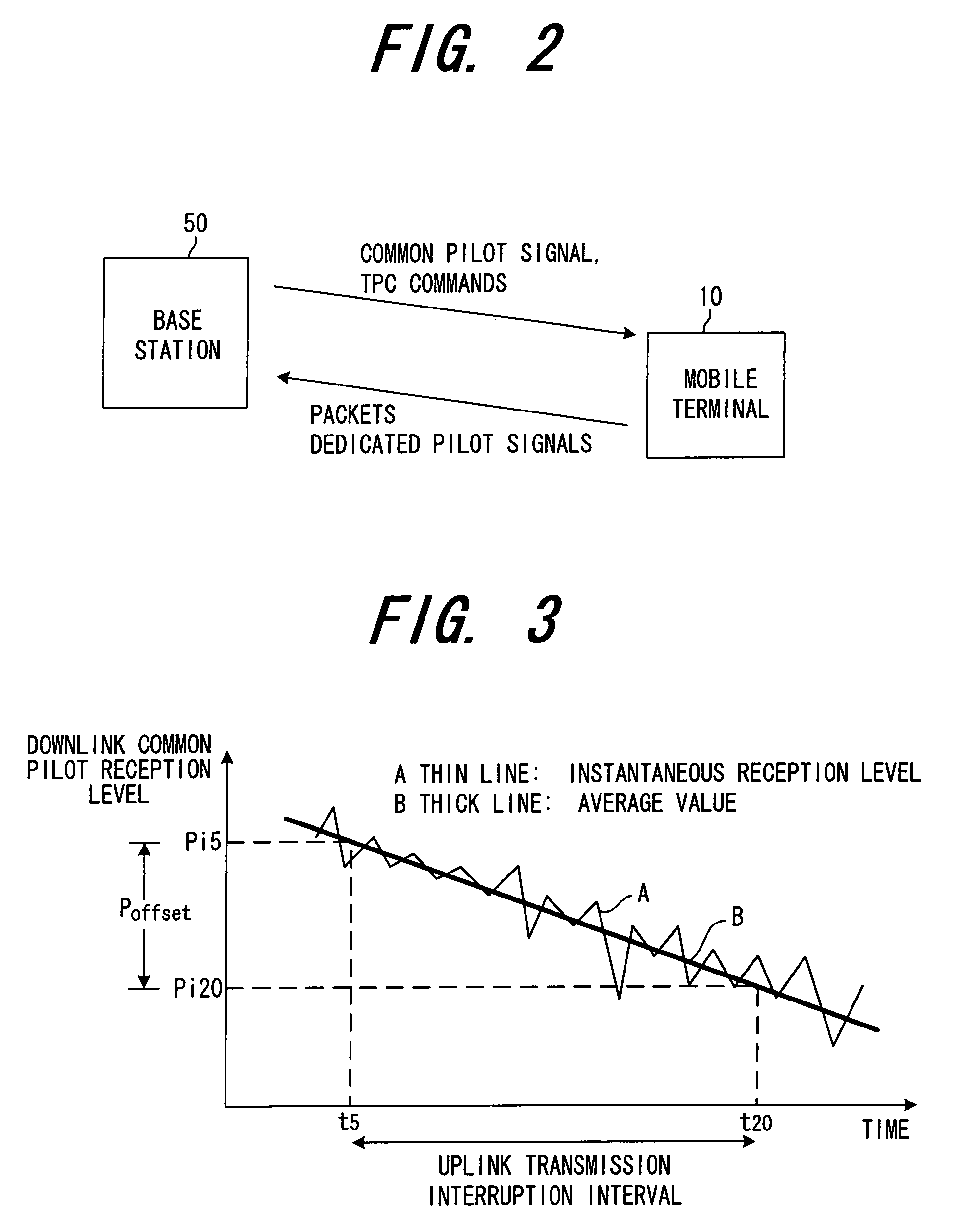
[0043]FIG. 1 shows the configuration of principal portions of a mobile terminal comprising transmission power control functions of this invention, and FIG. 2 is an explanatory diagram of uplink and downlink transmission and reception signals.

[0044]As shown in FIG. 2, similarly to the technology of the prior art in FIG. 7, the base station 50 measures reception quality based on dedicated pilot signals received from the mobile terminal 10, and creates and transmits to the mobile terminal 10, via the dedicated physical channel DPCH, TPC bits (TPC commands) at each slot, such that the measured reception quality approaches a target reception quality. In addition, the base station 50 constantly transmits a common pilot signal via the common pilot channel CPICH.

[0045]The transmission / reception antenna 11 (FIG. 1) of the mobile terminal 10 receives signals transmitted from the base station 50, and inputs the received signals to a radio portion 13 via a b...

second embodiment

(B) Second Embodiment

[0061]FIG. 5 shows the configuration of a second embodiment of the invention; portions which are the same as in the first embodiment are assigned the same symbols. A difference with the first embodiment is the fact that an UL / DL frequency ratio correction portion 31 is provided, which corrects the signal transmission power PUP at the time transmission is resumed according to the ratio of the RF signal frequency of downlink DL transmission from the base station to the mobile terminal, to the RF signal frequency of uplink UL transmission from the mobile terminal to the base station.

[0062]Even when there is a difference between the downlink DL RF signal frequency and the uplink UL RF signal frequency, if the ratio of the two frequencies is nearly equal to 1, then the moving average values Pavr of the reception levels at the base station and at the mobile terminal are substantially the same, and the transmission power at the time of transmission resumption can be de...

third embodiment

(C) Third Embodiment

[0065]FIG. 6 shows the configuration of a third embodiment of the invention; portions which are the same as in the first embodiment are assigned the same symbols. A difference with the first embodiment is the fact that the average number (number of slots) used when averaging the reception level of the common pilot signal is made variable. The fading environment (fading frequency) fluctuates according to the movement speed of the mobile terminal; the common pilot signal reception level changes greatly as the movement speed increases. Hence when the movement speed of the mobile terminal is slow, the number of slots used in calculating the moving average is reduced, and when the movement speed is fast, the number of slots used in calculating the moving average is increased.

[0066]By this means, when the movement speed is slower the number of slots used in calculating the moving average is reduced, so that accurate and responsive control is possible; and when the move...


PUM


Abstract

A base station creates and transmits power control data to a mobile terminal at each prescribed time slot based on signals received from the mobile terminal, and the mobile terminal controls the transmission power of signals to the base station based on the power control data. During this transmission power control, the mobile terminal measures the reception level of common pilot signals transmitted from the base station at each time slot, calculates a moving average of the reception level for a plurality of time slots, and when transmission to the base station is interrupted, stores the transmission power and moving average for the immediately preceding time slot, and when transmission to the base station is resumed, adds the difference between the moving average at the time of transmission resumption and the stored moving average to the stored transmission power, and uses the power obtained by this addition as the signal transmission power at the time of transmission resumption.

Description

BACKGROUND OF THE INVENTION[0001]This invention relates to a transmission power control method and a mobile terminal apparatus, and in particular relates to a transmission power control method for a mobile terminal when resuming transmission after transmission has been interrupted, and to a mobile transmission apparatus.[0002]Specifications for radio communication systems using W-CDMA have been prepared by the 3rd Generation Partnership Project (3GPP), and actual services based on them are already in operation in many countries including Japan. FIG. 7 is a summary diagram of the configuration of a radio communication system. A 3GPP radio access system comprises a base station control apparatus (radio network controller) 1, base stations (node B) 2, 3, . . . , and mobile terminals (user equipment) 4, 5, . . . The base station control apparatus 1 is connected to the core network 6 via an Iu interface, and is connected to base stations 2, 3 via an Iub interface.[0003]In a mobile commun...

Claims


Application Information

Patent Timeline
Patent Type & Authority Patents(United States)
IPC IPC(8): H04B7/00H04W52/04H04W52/44
CPCH04W52/44H04W52/04
Inventor KAWASAKI, YOSHIHIRO
Owner FUJITSU LTD
Learn More