Chip for force sensor and force sensor

a technology of force sensor and chip, which is applied in the direction of force/torque/work measurement apparatus, instruments, generators/motors, etc., can solve the problems of small difference in crystal orientation between the surface, damage to the force sensor chip, and non-uniform characteristics of the strain resistance element, so as to prevent the damage of the force sensor chip and improve the uniformity of the characteristics of a plurality of strain resistance elements

Active Publication Date: 2010-04-27
HONDA MOTOR CO LTD
View PDF16 Cites 13 Cited by
  • Summary
  • Abstract
  • Description
  • Claims
  • Application Information

AI Technical Summary

Benefits of technology

[0012]In the arrangement of the strain resistance elements described above, since the plurality of strain resistance elements are oriented in a same direction, a physical property of each of the strain resistance elements such as a piezoresistive coefficient can be made equal, even if there is a difference in orientation between a surface of the base member and the crystal orientation. As a result, uniformity of the physical property of the strain resistance elements can be improved.
[0034]According to the present invention, uniformity of characteristics of a plurality of strain resistance elements can be improved.

Problems solved by technology

Meanwhile, if the applied external force is directly transmitted to the strain resistance elements, the force sensor chip may be damaged when the force is too large.
However, a small difference in crystal orientation is produced between the surface and the crystal orientation by a semiconductor substrate manufacturing process.
If a plurality of the strain resistance elements are arranged orthogonally on the semiconductor substrate described above, a physical constant such as a piezoresistive coefficient becomes different among the elements, thereby resulting in non-uniform characteristics among the strain resistance elements.
If the force sensor chips described above are applied to the multiaxial force sensor, a correction of non-uniformity is required among detected values because of the non-uniform characteristics among the strain resistance elements, thereby resulting in complexity of signal processing.

Method used


Image

  • Chip for force sensor and force sensor
  • Chip for force sensor and force sensor
  • Chip for force sensor and force sensor

Examples


Embodiment Construction

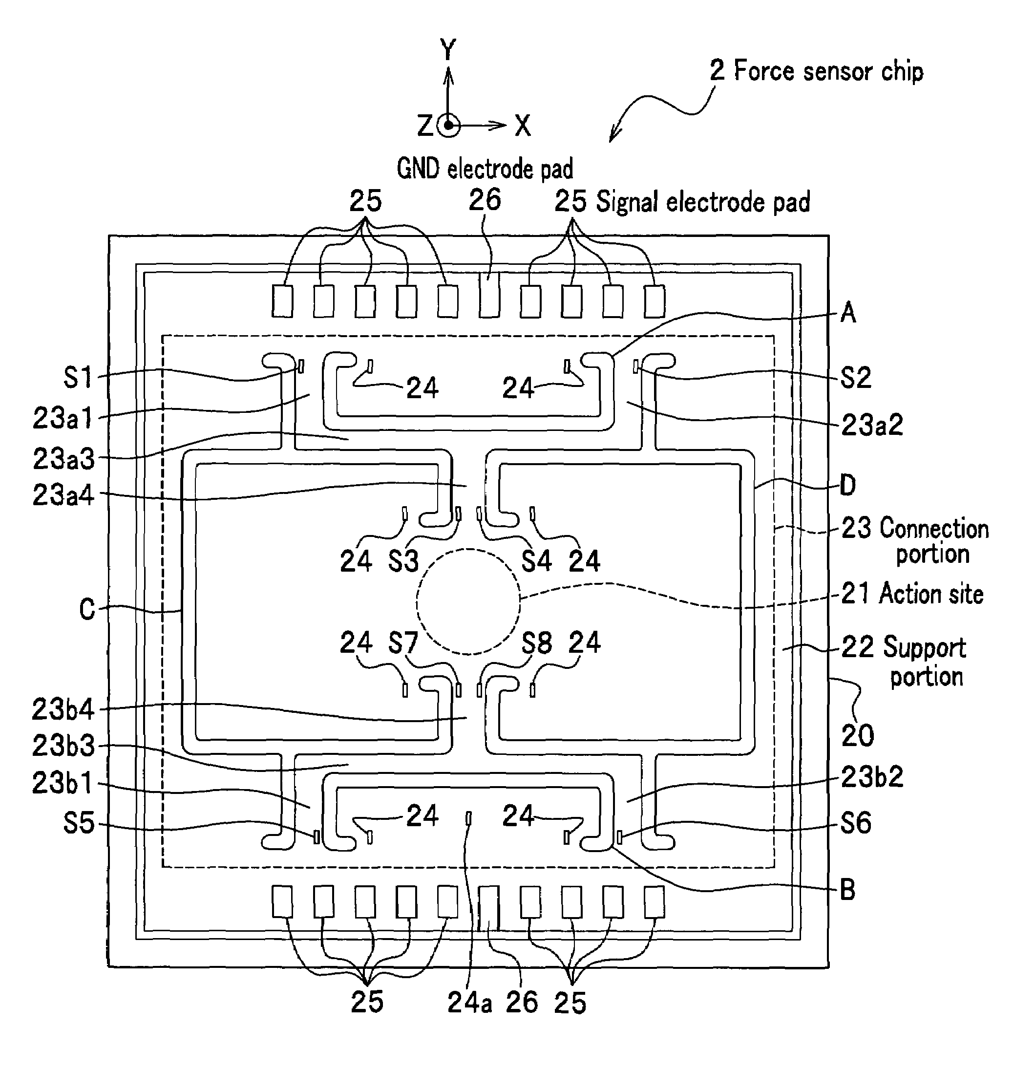
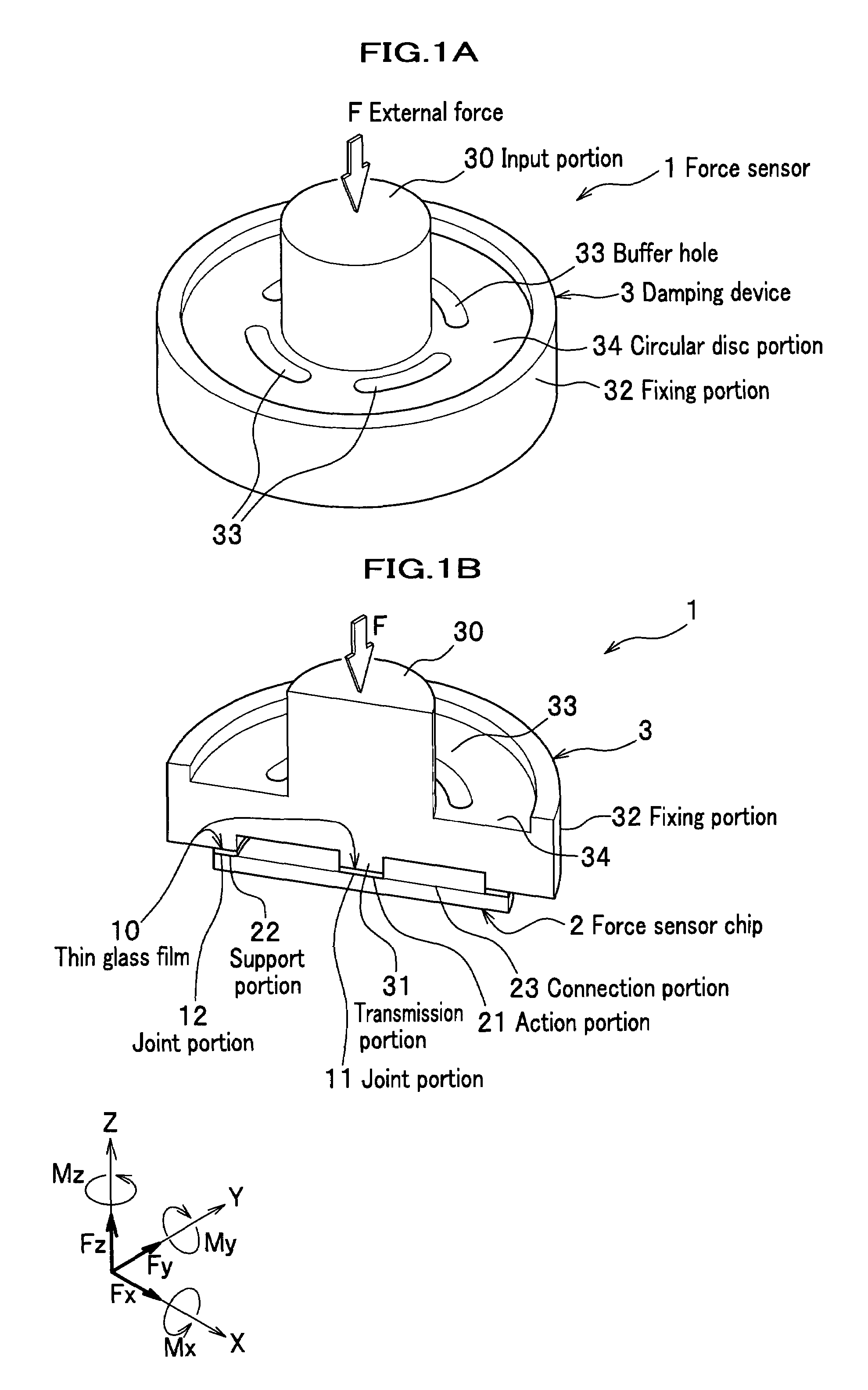
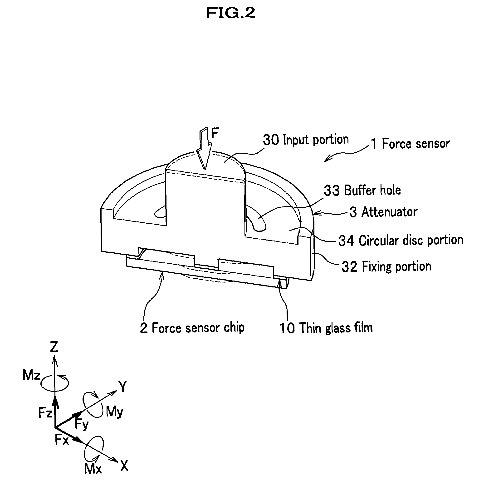
[0056]First, a whole composition of a force sensor according to an embodiment of the present invention will be explained by referring to FIG. 1A to FIG. 3. FIG. 1A is a perspective view for explaining a brief constitution of a force sensor according to an embodiment of the present invention and showing an outer shape of the force sensor. FIG. 1B is a perspective view for explaining a brief constitution of the force sensor according to the embodiment and showing a cross section of an internal structure of the force sensor. FIG. 2 is a cross sectional perspective view schematically showing an external force which is attenuated and transmitted to a force sensor chip. FIG. 3 is a plane view showing a main part of a force sensor chip for explaining the force sensor chip according to the embodiment in detail.

[0057]It is noted that for convenience, for example, a degree of strain and an appearance at a joint portion may be emphasized in the views in some cases.

[0058]As shown in FIG. 1A and...


PUM

PropertyMeasurementUnit
thicknessaaaaaaaaaa
forceaaaaaaaaaa
external forceaaaaaaaaaa

Abstract

A force sensor chip which comprises: a base member, which includes an action portion to which an external force is applied through an attenuator, a support portion supporting the action portion, and a connection portion which connects the action portion and the support portion and deflects according to the applied external force; and a plurality of strain resistance elements which are arranged in the connection portion and detect the applied external force based on a deflection of the connection portion, wherein longitudinal directions of the plurality of the strain resistance elements are oriented in an identical direction.

Description

CROSS REFERENCE TO RELATED APPLICATIONS[0001]This application claims the foreign priority benefit under Title 35, United States Code, §119(a)-(d) of Japanese Patent Application No. 2006-234585, filed on Aug. 30, 2006, the contents of which are hereby incorporated by reference.BACKGROUND OF THE INVENTION[0002]1. Field of the Invention[0003]The present invention relates to a force sensor chip and a force sensor, and particularly relates to the force sensor chip and the force sensor which detect an applied external force using a plurality of strain resistance elements.[0004]2. Description of Related Art[0005]Conventionally, a multiaxial force sensor which precisely detects a strength and direction of an applied external force is used, for example, for industrial robots for correctly and flexibly controlling the external force applied during operations.[0006]For example, a multiaxial force sensor which utilizes a property of a strain resistance element (piezoresistive element) is known,...

Claims


Application Information

Patent Timeline
Patent Type & Authority Patents(United States)
IPC IPC(8): G01L1/22G01D7/00G01L1/00H01L41/00G01L5/16
CPCG01L5/162
Inventor SAKURAI, NOBUHIROOHSATO, TAKESHI
Owner HONDA MOTOR CO LTD
Why Eureka
Try Eureka