Dynamic SPECT camera

a spectrometer and dynamic technology, applied in the field ofspect nuclear imaging, can solve the problems of not providing spectral information for pet imaging, not distinguishing between radio-isotopes, etc., and achieve the effect of short damping tim

Active Publication Date: 2010-04-27
SPECTRUM DYNAMICS MEDICAL LTD
View PDF210 Cites 60 Cited by
  • Summary
  • Abstract
  • Description
  • Claims
  • Application Information

AI Technical Summary

Benefits of technology

[0036]The present invention relates to a dynamic SPECT camera, which comprises, a plurality of single-pixel detectors, a timing mechanism, in communication with each single-pixel detector, configured for enabling time-binning of the radioactive emissions impinging upon each single-pixel detector to time periods not greater than substantially 30 seconds, and a position-tracker, configured for providing information on the position and orientation of each single-pixel detector, with respect to the overall structure, substantially at all times, during the individual motion, the dynamic SPECT camera being configured for acquiring a tomographic reconstruction image of a region of interest of about 15×15×15 cubic centimeters, during an acquisition time of 30 seconds, at a spatial resolution of at least 10×10×10 cubic millimeter. The dynamic camera is further configured for very short damping time, when in stop and shoot acquisition mode and may further acquire images in a stationary mode, with no motion. It is further configured for time binning at dynamically varying time-bin lengths, dynamically determining a spectral energy bin for each single-pixel detector, and constructing and employing an anatomic system of voxels in the imaging and reconstruction.

Problems solved by technology

Yet, since the annihilation gamma is of 0.511 Mev, regardless of the radio-isotope, PET imaging does not provide spectral information, and does not differentiate between radio-isotopes.
There are several disadvantages to this system, for example:1. the dedicated algorithms associated with the single pixel cannot reach the accuracy of a two-dimensional image of a plurality of single pixel detectors;2. the single-pixel detector is a rigid unit, which does not have the flexibility of motion of a plurality of small detectors, each with independent motion; and3. a single hot spot may cause the single pixel detector of the Anger camera to saturate, whereas when a plurality of single pixel detectors is employed, saturation is localized to a few pixels and does not affect the whole image.

Method used


Image

  • Dynamic SPECT camera
  • Dynamic SPECT camera
  • Dynamic SPECT camera

Examples


Embodiment Construction

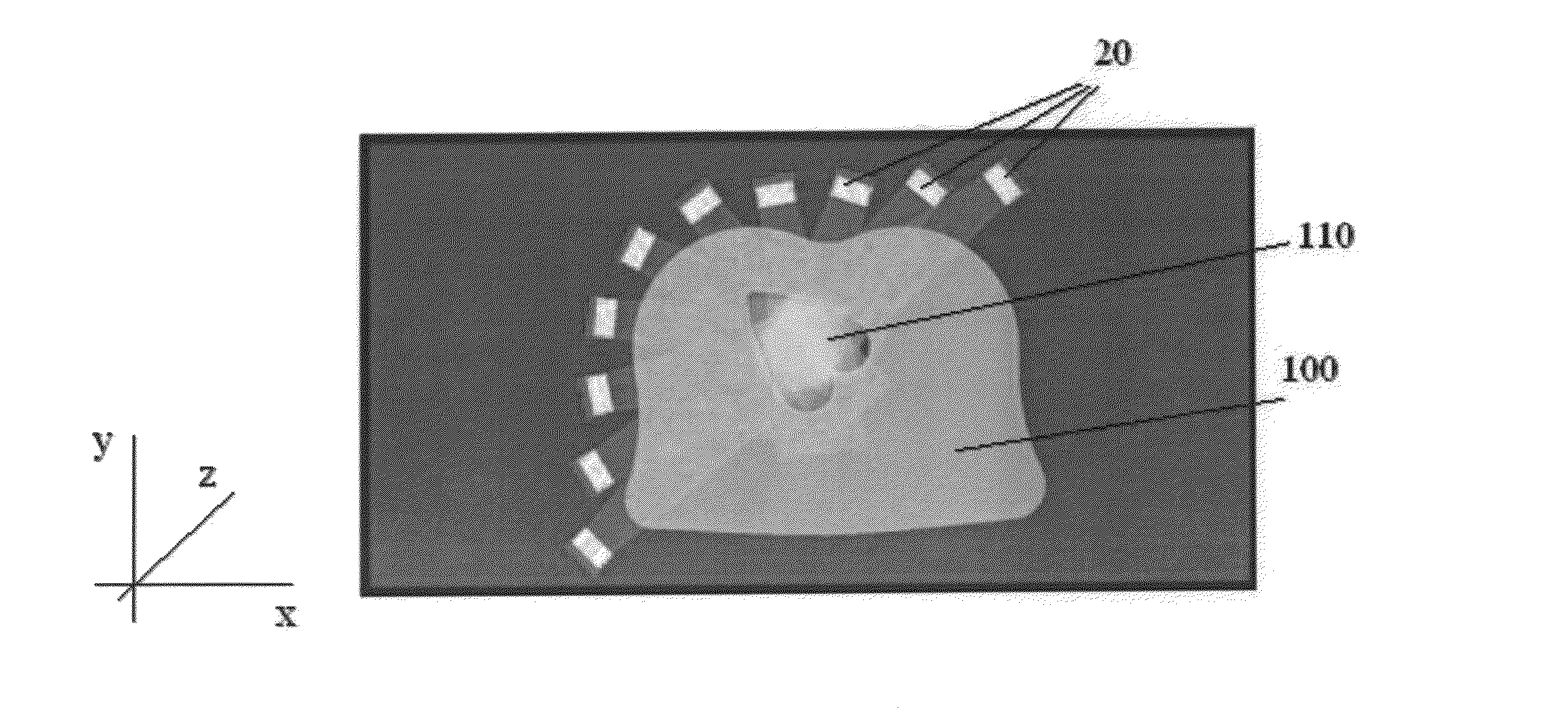
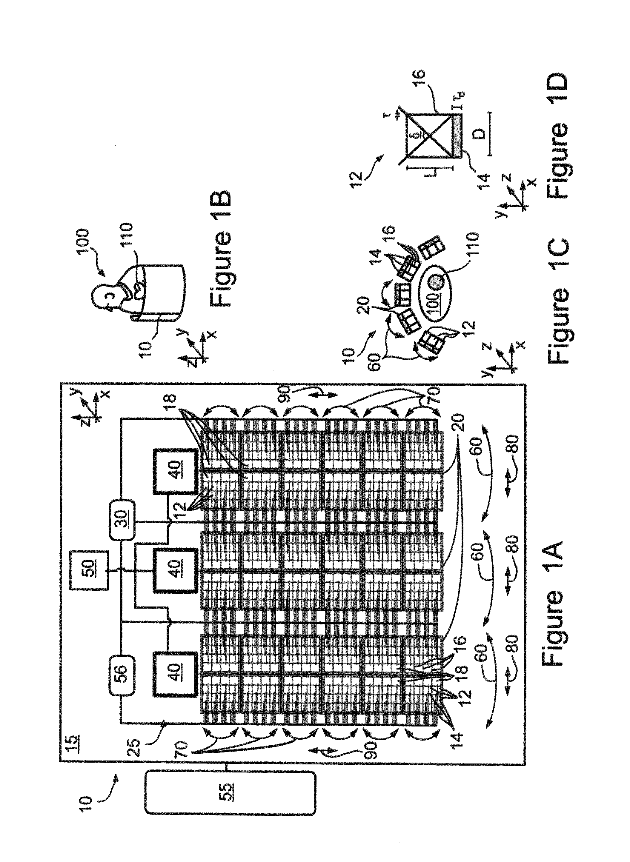
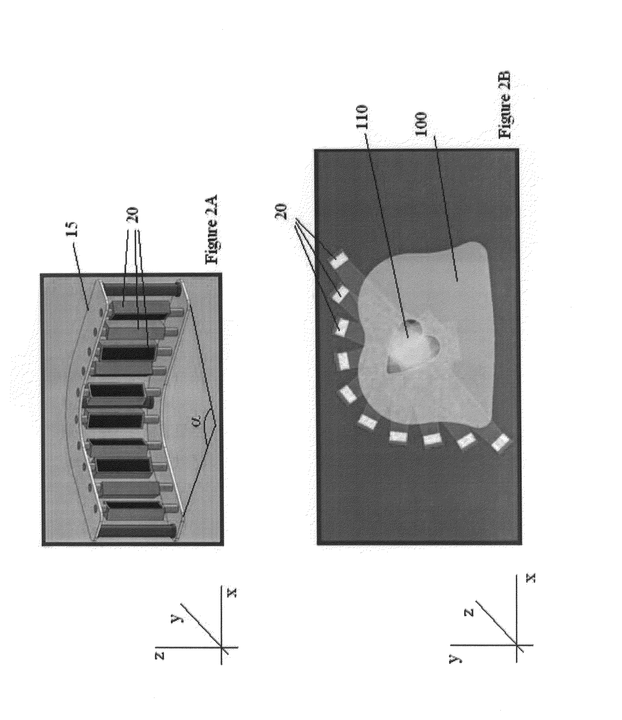
[0055]The present invention relates to a dynamic SPECT camera, which comprises, a plurality of single-pixel detectors, a timing mechanism, in communication with each single-pixel detector, configured for enabling time-binning of the radioactive emissions impinging upon each single-pixel detector to time periods not greater than substantially 30 seconds, and a position-tracker, configured for providing information on the position and orientation of each single-pixel detector, with respect to the overall structure, substantially at all times, during the individual motion, the dynamic SPECT camera being configured for acquiring a tomographic reconstruction image of a region of interest of about 15×15×15 cubic centimeters, during an acquisition time of 30 seconds, at a spatial resolution of at least 10×10×10 cubic millimeter. The dynamic camera is further configured for very short damping time, when in stop and shoot acquisition mode and may further acquire images in a stationary mode, ...


PUM


Abstract

A dynamic SPECT camera is provided, comprising, a plurality of single-pixel detectors, a timing mechanism, in communication with each single-pixel detector, configured for enabling time-binning of the radioactive emissions impinging upon each single-pixel detector to time periods not greater than substantially 30 seconds, and a position-tracker, configured for providing information on the position and orientation of each detecting unit, with respect to the overall structure, substantially at all times, during the individual motion, the dynamic SPECT camera being configured for acquiring a tomographic reconstruction image of a region of interest of about 15×15×15 cubic centimeters, during an acquisition time of 30 seconds, at a spatial resolution of at least 10×10×10 cubic millimeter. The dynamic camera is configured for very short damping time, and may further acquire images in a stationary mode, with no motion. It is further configured for time binning at dynamically varying time-bin lengths, dynamically determining a spectral energy bin for each detecting unit, and employing an anatomic construction of voxels in the imaging and reconstruction.

Description

RELATED APPLICATIONS[0001]This application is a National Phase Application of PCT Application No. PCT / IL2006 / 001291 having International Filing Date of Nov. 9, 2006, which claims priority from PCT Applications Nos. PCT / IL2006 / 000840 and PCT / IL2006 / 000834, both filed on Jul. 19, 2006, U.S. Provisional Patent Application No. 60 / 816,970, filed on Jun. 28, 2006, U.S. Provisional Patent Applications Nos. 60 / 800,846 and 60 / 800,845, both filed on May 17, 2006, U.S. Provisional Patent Application No. 60 / 799,688, filed on May 11, 2006, PCT Application No. PCT / IL2006 / 000562, filed on May 11, 2006, U.S. Provisional Patent Application No. 60 / 763,458, filed on Jan. 31, 2006, PCT Application No. PCT / IL2006 / 000059, filed on Jan. 15, 2006, U.S. Provisional Patent Application No. 60 / 754,199, filed on Dec. 28, 2005, U.S. Provisional Patent Applications Nos. 60 / 750,597 and 60 / 750,334, both filed on Dec. 15, 2005, U.S. Provisional Patent Application No. 60 / 750,287, filed on Dec. 13, 2005, U.S. Provisio...

Claims


Application Information

Patent Timeline
Patent Type & Authority Patents(United States)
IPC IPC(8): G01T1/24
CPCG01T1/161A61B6/037G01T1/2985G01T1/166
Inventor ROUSSO, BENNYZIV, OMERNAGLER, MICHAELBEN-HAIM, SHLOMO
Owner SPECTRUM DYNAMICS MEDICAL LTD
Why Eureka
Try Eureka