
Digital power supply control

a digital power supply and control technology, applied in the direction of dc-dc conversion, power conversion systems, instruments, etc., can solve the problems of high cost and complexity of voltage regulation arrangement, analog pulse width modulator performance, and general higher cost of analog pulse width modulator

Inactive Publication Date: 2010-04-27
VIRGINIA TECH INTPROP INC
View PDF11 Cites 18 Cited by
  • Summary
  • Abstract
  • Description
  • Claims
  • Application Information

AI Technical Summary

Benefits of technology

The present invention provides a practical digital pulse width modulation (DPWM) arrangement in a switching voltage regulator that can hold the amplitude of limit cycle oscillations to low and predictable levels. This is achieved by using a power converter with a digital pulse width modulator of low resolution that causes limit cycle oscillations. The feedback control arrangement includes a sampling arrangement and analog to digital converter, an outer control loop, and an inner control loop. The method of voltage regulation involves providing an average of the output voltage of the voltage regulator in an outer feedback loop to the digital pulse width modulator, and a signal corresponding to a difference between the output voltage of the voltage regulator and the average in an inner feedback loop to the digital pulse width modulator. This results in a more stable and accurate voltage regulation.

Problems solved by technology

Efficiency of the power supply and voltage regulation arrangement is also of high importance, along with cost and complexity of the voltage regulation arrangement.
Analog pulse width modulators have provided good performance but are generally more expensive, subject to noise and often require designs to be specific to particular applications.
However, an analog power stage (e.g. a switching regulator having analog components) with a digital control loop makes system control more complicated since two quantizers, a digital pulse width modulator (DPWM) 10 and an analog to digital (A / D) converter 20 are introduced into the control loop as shown in FIG. 1.
Such limit cycle oscillations and their amplitude and waveform, in particular, are difficult to predict but are significantly more likely to occur using a low resolution DPWM than when using a high resolution DPWM.
Thus it is clearly seen that there is a significant trade-off between cost of the A / D converter and DPWM to obtain a given degree of duty cycle resolution and the ability to reliably regulate voltage within a given voltage tolerance.
Accordingly, it is seen from FIG. 4 that the system clock (fclock) requirement to achieve a 3 mV output voltage resolution (notwithstanding limit cycle oscillations as shown in FIG. 5) under different switching frequency (fsw) conditions generally exceed 1 GHz for common or increased fsw which is not feasible for practical implementations.

Method used


Image

  • Digital power supply control
  • Digital power supply control
  • Digital power supply control

Examples


Embodiment Construction

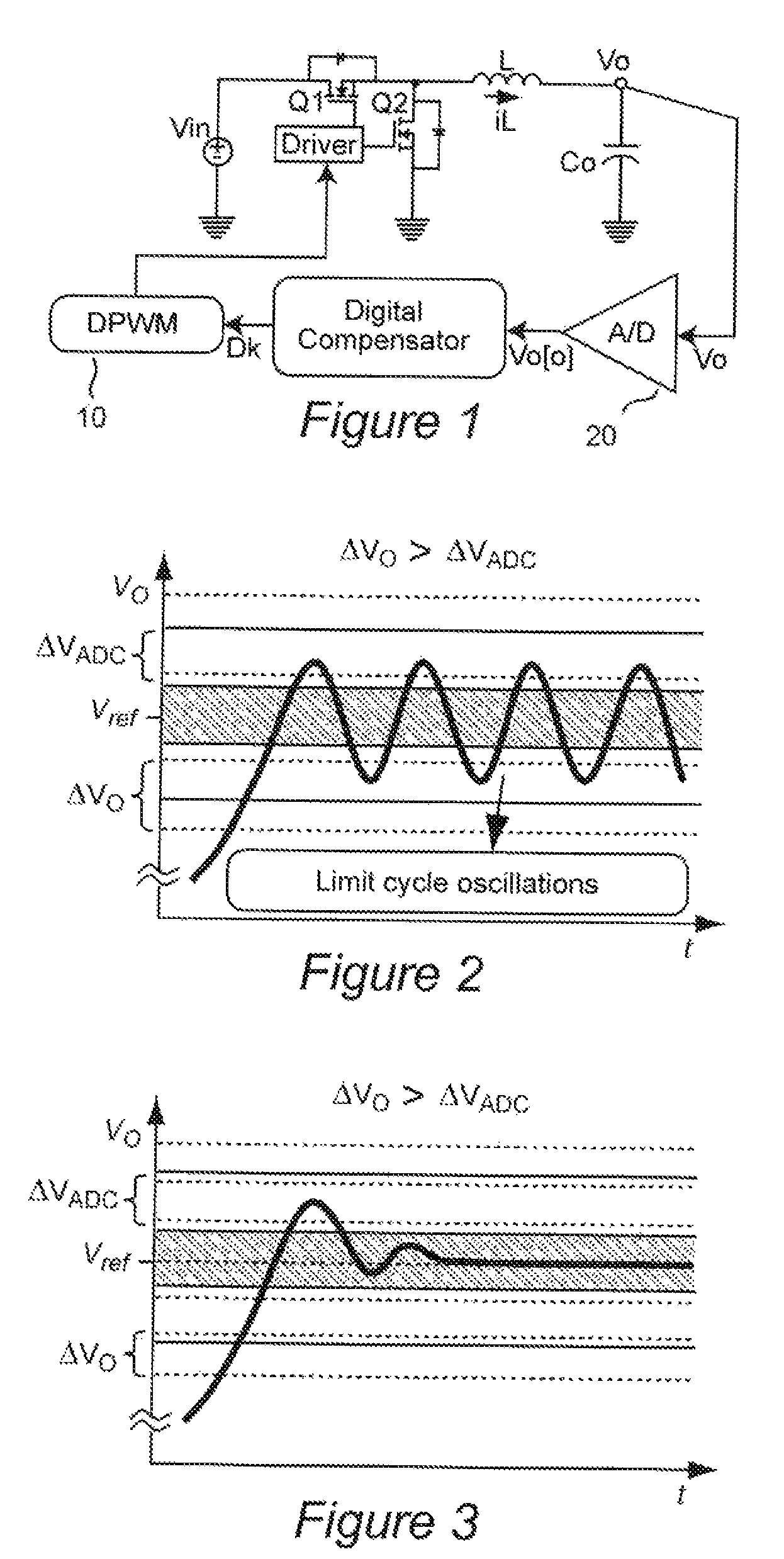
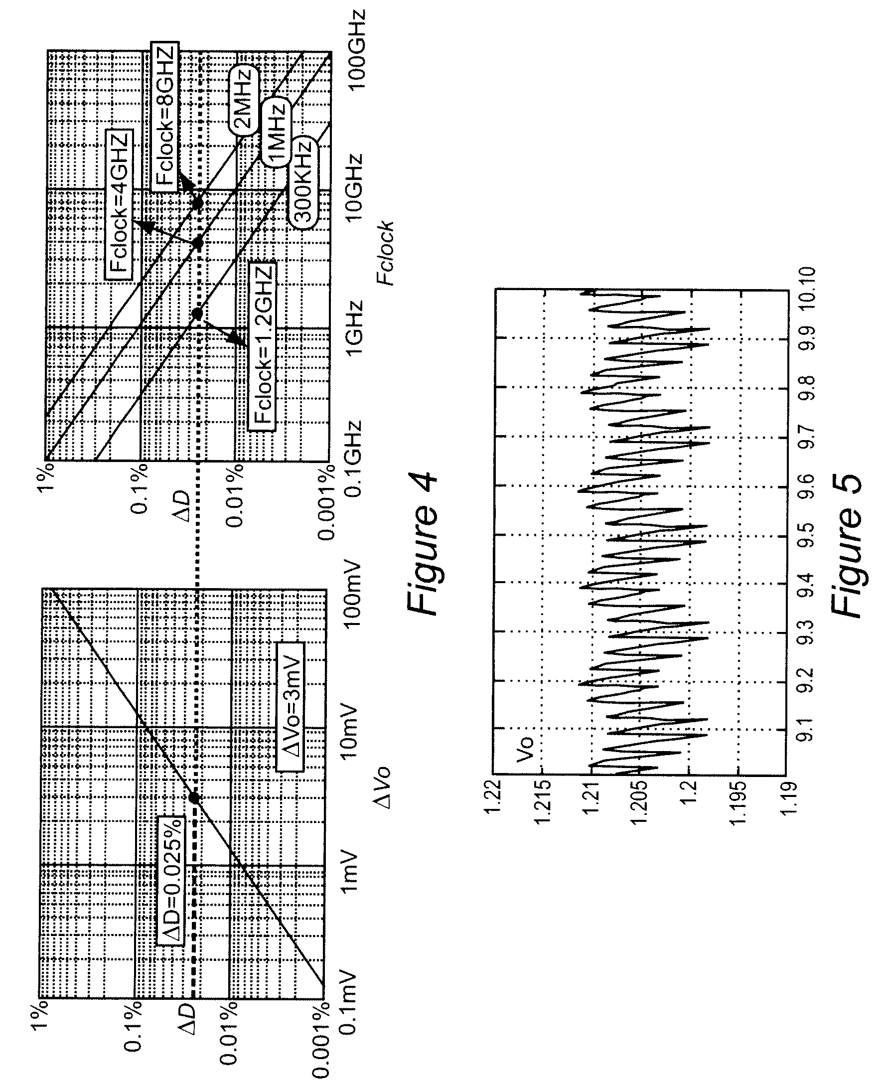
[0027]Referring now to the drawings, and more particularly to FIGS. 1-4, as discussed above, it is clearly seen that high clock rates are not practical for achieving adequately high voltage resolution while using a relatively low resolution digital pulse width modulator (DPWM). As an alternative to such high system clock frequencies, use of delay lines has been proposed but requires an impractical amount of chip space. Dithering techniques have also been proposed to increase the effective resolution of the DPWM but additional voltage ripple is caused by the dithered duty cycle which limits the potential benefits of such techniques. As can be readily appreciated from the waveforms of limit cycle oscillations as illustrated in FIG. 5, not only does the voltage oscillate at a high frequency but, under load, the high-frequency voltage oscillations are effectively superimposed on a lower frequency near-sinusoidal ripple having a magnitude which is, by itself, comparable to the maximum am...


PUM


Abstract

A switched voltage regulator provides improved regulation at a lower clock rate / sampling frequency (e.g. several orders of magnitude lower than would be required for comparable regulation) while using a low resolution digital pulse width modulator such that limit cycle oscillations occur (and thus of low cost and complexity and small size) by limiting the amplitude of limit cycle oscillations which therefore need not be avoided by more complex arrangements which are not commercially feasible. Limiting of amplitude of limit cycle oscillations is achieved by adding essentially a digitized ripple voltage signal corresponding to the difference between the output of the voltage regulator and an average output of the voltage regulator as an input to the digital pulse width modulator. Performance of this arrangement may be enhanced by adding a ramp signal to the digitized ripple voltage signal and even further enhanced by limiting the ramp signal to a range which corresponds to steady state operation but not transients.

Description

BACKGROUND OF THE INVENTION[0001]1. Field of the Invention[0002]The present invention generally relates to control of power supplies and voltage regulators / power converters and, more particularly, to high-resolution control of voltage regulation with digital pulse width modulation arrangements of reduced resolution and consequent reduced complexity and cost.[0003]2. Description of the Prior Art[0004]Many types of electrical and electronic devices require power at a substantially constant voltage, although the tolerance for voltage variation of the power supply can vary widely. However, in general, voltage regulation within a relatively small tolerance over a wide range of current loads is highly desirable even though the current load can cause variation in the voltage supplied. Efficiency of the power supply and voltage regulation arrangement is also of high importance, along with cost and complexity of the voltage regulation arrangement.[0005]For these reasons, switching power supp...

Claims


Application Information

Patent Timeline
Patent Type & Authority Patents(United States)
IPC IPC(8): G05F1/00
CPCH02M3/157
Inventor LI, JIANQIU, YANGXU, MINGLEE, FRED C.
Owner VIRGINIA TECH INTPROP INC
Learn More