
Electrical overstress (EOS) and electrostatic discharge (ESD) protection circuit and method of use

a protection circuit and electrostatic discharge technology, applied in the direction of transistors, electrical devices, arrangements responsive to excess voltage, etc., can solve the problems of shrinking in size, easy damage to internal circuitry of integrated circuit devices, and becoming more susceptible to electrostatic discharge damag

Inactive Publication Date: 2010-04-27
INTEGRATED DEVICE TECH INC
View PDF7 Cites 26 Cited by
  • Summary
  • Abstract
  • Description
  • Claims
  • Application Information

AI Technical Summary

Benefits of technology

[0006]In accordance with the present invention, a system and method are provided to reduce the power line overshoot or undershoot during power-up. The present invention employs circuitry to establish a slow down path which delays the turn off of the ESD device.
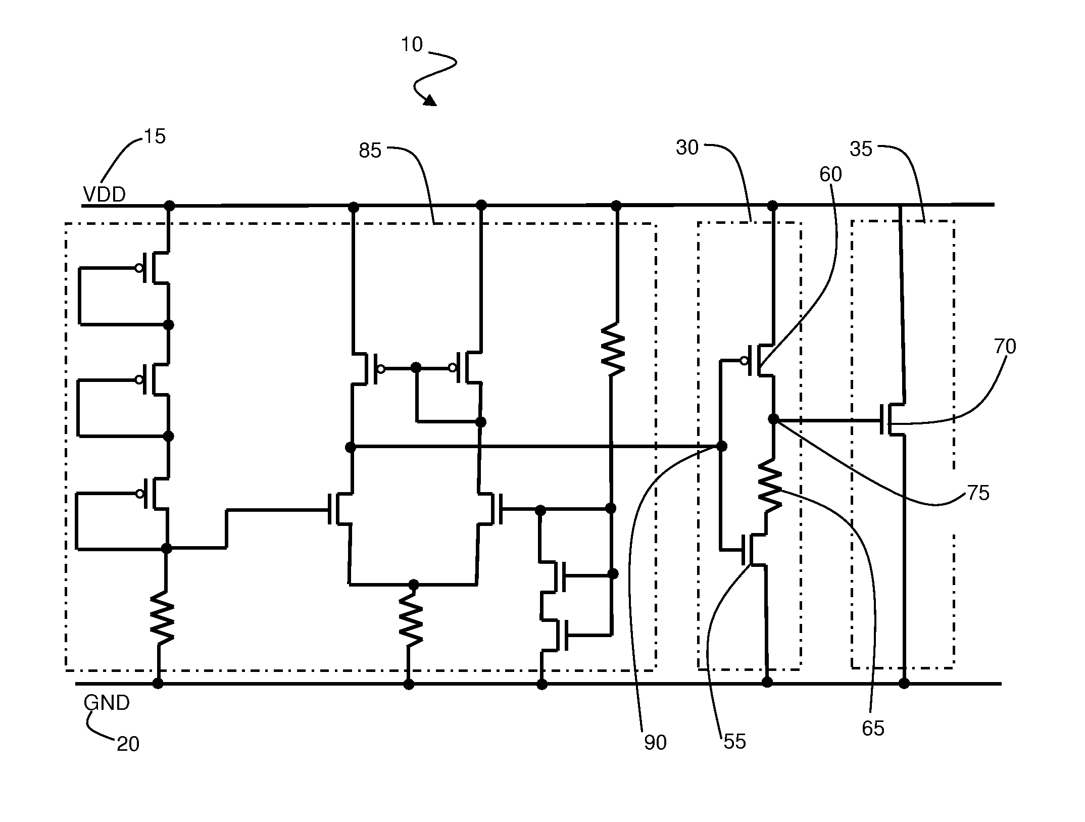
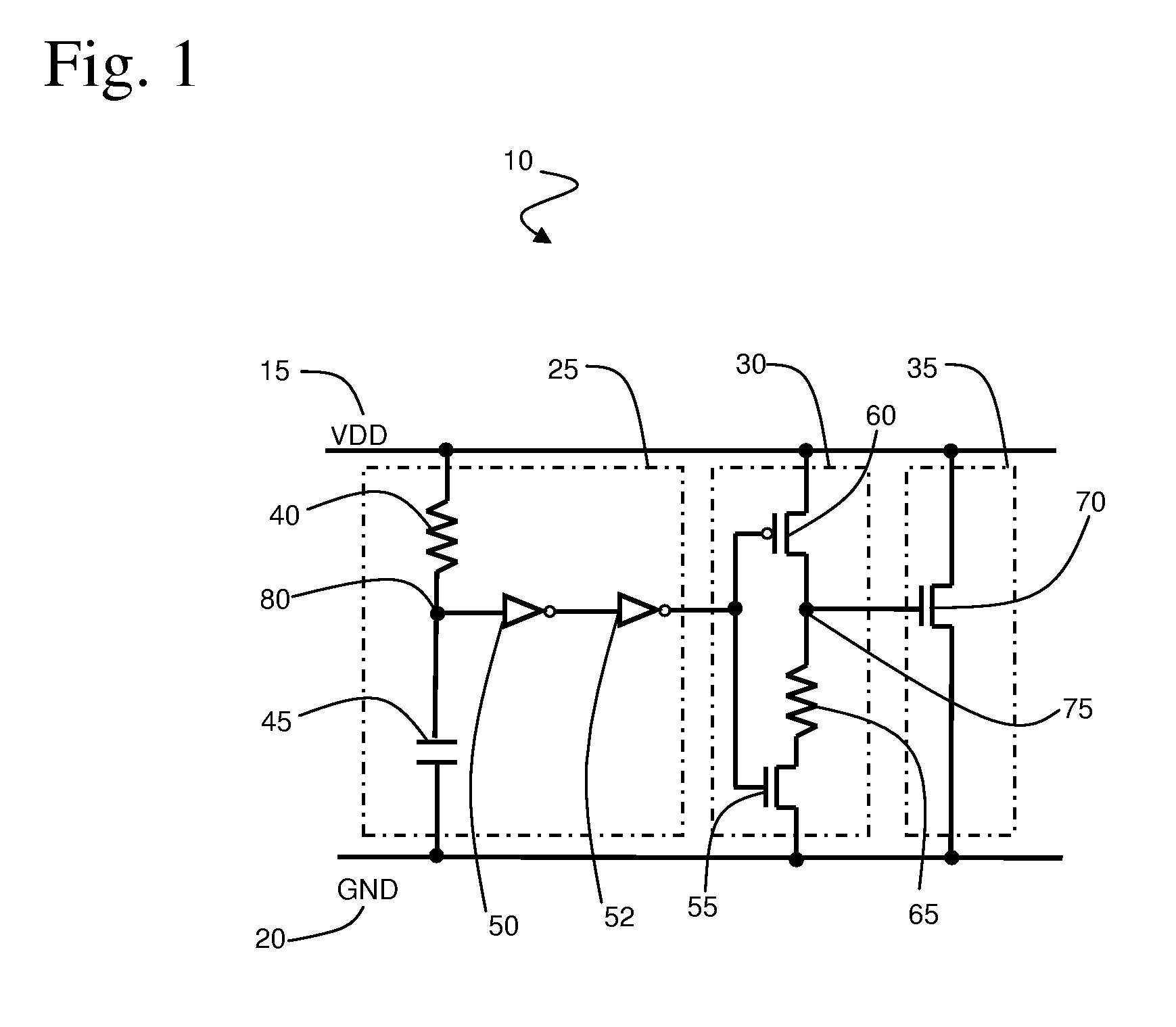
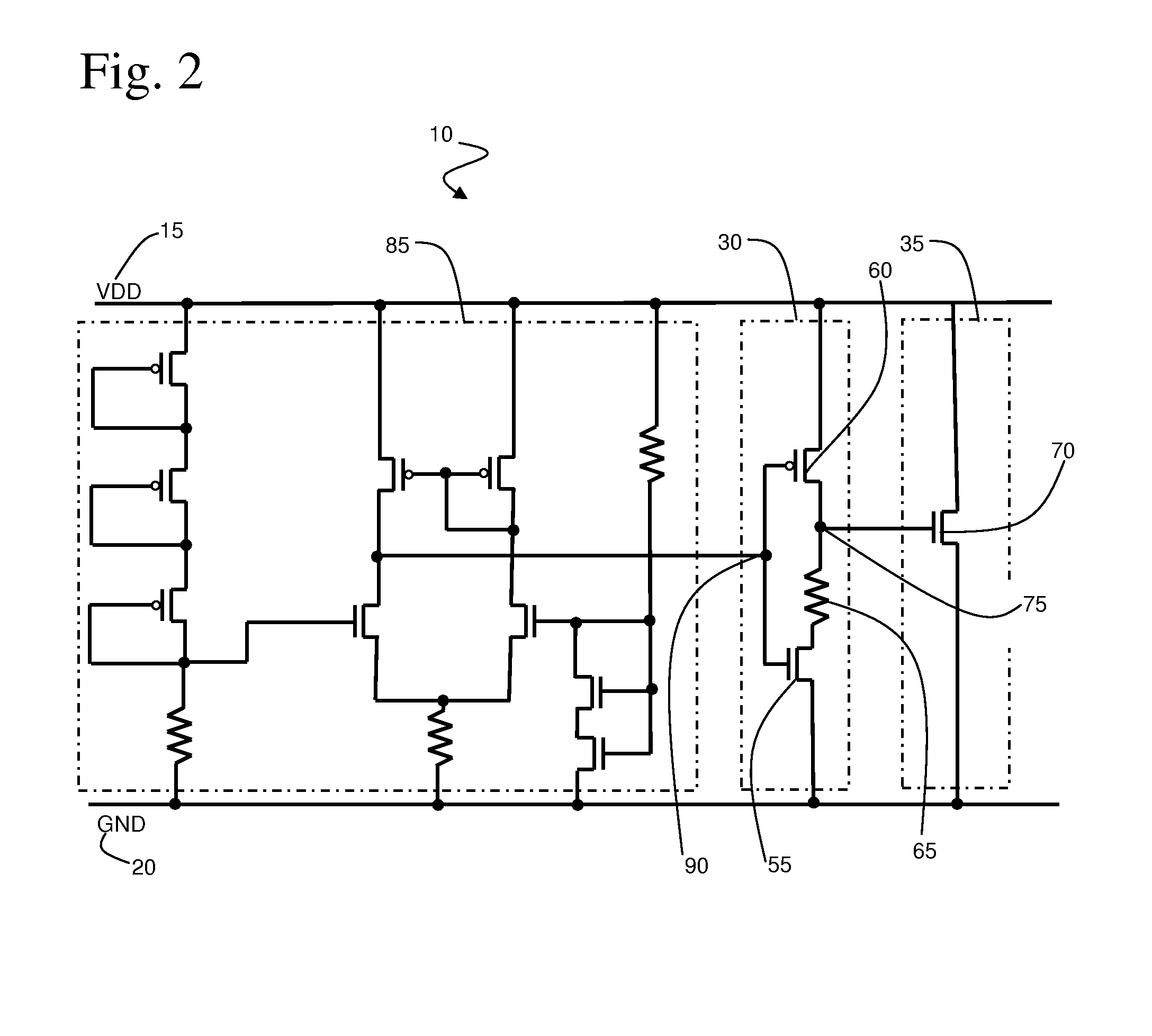
[0007]In accordance with an embodiment of the present invention, an electrostatic discharge (ESD) protection circuit is provided having overshoot and undershoot voltage protection during a power supply ramp-up of the circuit, the circuit includes an ESD discharge circuit coupled between a power supply node and a ground supply node, a trigger circuit coupled to the ESD discharge circuit and a delay circuit coupled between the discharge circuit and the trigger circuit. The trigger circuit in accordance with the present invention turns the ESD discharge circuit on in the presence of a voltage spike during the power supply ramp-up and turns the ESD discharge circuit off in the absence of a voltage spike during the power supply ramp-up. The delay element in accordance with the present invention is effective in slowing down the turn-off of the discharge circuit to prevent an overshoot or undershoot voltage condition during the power supply ramp-up of the circuit.
[0010]The delay circuit in accordance with the present invention is effective in slowing down the turn-off of the discharge circuit to prevent an overshoot or undershoot condition. In a particular embodiment, the delay circuit includes an inverter having a pull-up transistor and a pull-down transistor and a resistive element positioned between an output of the inverter and a drain node of the pull-down transistor. More specifically, the pull-up transistor of the delay circuit has a gate node coupled to the trigger circuit, a source node coupled to the power supply and a drain node coupled to the discharge circuit. The pull-down transistor of the delay circuit has a gate node coupled to the trigger circuit and a source node coupled to a ground node and the resistive element is then coupled between the discharge circuit and a drain node of the pull-down transistor.
[0013]In a specific embodiment, the turn-off delay circuit includes at least one inverter and at least one NOR gate coupled between a triggering input to the turn-off signal delay stage circuit and the delay circuit. The combination of the inverters and the NOR gates is effective in delaying the transmission of the turn-off signal to the delay circuit but does not delay the transmission of the turn-on signal to the delay circuit. In addition, the number of inverters and NOR gates may be varied for each of the individual ESD protection circuits such that the delay time may be different for each of the plurality of ESD circuits and as such, the turn-off signal transmission for each of the plurality of ESD circuits will be staggered, each contributing to the total turn-off delay of the ESD protection circuit. As such, the total turn-off current is more precisely controlled and the overshoot voltage is further reduced when using multiple ESD protection circuits within an integrated circuit device.
[0014]In accordance with the present invention, a method for preventing damage to an electrostatic discharge (ESD) protection circuit when a discharge circuit of the ESD circuit is unintentionally turned-on during power-up of the ESD protection circuit is provided. The method of the present invention results in a delayed turn-off of the discharge circuit to prevent an overshoot or undershoot voltage condition thereby preventing damage to the ESD protection circuit. The unintentional turn-on of the discharge circuit may be a result of noise on the power supply bus that is coupled to the ESD protection circuit.
[0016]As such, the present invention provides an improved active ESD-protection circuit that prevents an overshoot or undershoot condition when the ESD-protection circuit is unintentionally triggered during power-up of the integrated circuit.

Problems solved by technology

With advances in technology and the miniaturization of device elements in semiconductor integrated circuits, integrated circuits are becoming more susceptible to damage due to electrostatic discharge (ESD).
As a result, the internal circuitry of an integrated circuit device is easily damaged by an ESD event.
As semiconductors continue to shrink in size and become increasingly more complex, significant Electrical Overstress (EOS) and Electrostatic Discharge (ESD) become a greater challenge for both designers and manufacturers.
An EOS failure is typically catastrophic and causes permanent, irreparable damage to the integrated circuit device.
While such an active ESD-protection circuit is useful, it may be susceptible to noise, especially during power-up of the chip.
If the active ESD-protection circuit triggers during power-up, the quick turn off of the ESD clamping device may cause a power bus overshoot or undershoot.
The stress on the circuitry results from this overshoot or undershoot voltage can damage the ESD-protection circuit during power-up and cause power shorting through the damaged device.

Method used


Image

  • Electrical overstress (EOS) and electrostatic discharge (ESD) protection circuit and method of use
  • Electrical overstress (EOS) and electrostatic discharge (ESD) protection circuit and method of use
  • Electrical overstress (EOS) and electrostatic discharge (ESD) protection circuit and method of use

Examples


Embodiment Construction

[0022]Reference will now be made in detail to the preferred embodiments of the invention, examples of which are illustrated in the accompanying drawings. While the invention will be described in conjunction with the preferred embodiments, it will be understood that they are not intended to limit the invention to these embodiments. On the contrary, the invention is intended to cover alternatives, modifications and equivalents, which may be included within the spirit and scope of the invention as defined by the appended claims. Furthermore, in the following detailed description of the present invention, numerous specific details are set forth in order to provide a thorough understanding of the present invention. However, it will be obvious to one of ordinary skill in the art that the present invention may be practiced without these specific details. In other instances, well-known methods, procedures, components, and circuits have not been described in detail so as not to unnecessarily...


PUM


Abstract

A system and method are provided for electrostatic discharge (ESD) protection circuit having overshoot and undershoot voltage protection during a power supply ramp-up of the circuit. In a specific embodiment, the ESD protection circuit of the present invention includes an ESD discharge circuit coupled between a power supply node and a ground supply node, a trigger circuit coupled to the ESD discharge circuit, the trigger circuit to turn the ESD discharge circuit on in the presence of a voltage spike during the power supply ramp-up and to turn the ESD discharge circuit off in the absence of a voltage spike during the power supply ramp-up, and a delay circuit coupled between the discharge circuit and the trigger circuit, the delay circuit to slow down the turn-off of the discharge circuit to prevent an overshoot or undershoot voltage condition during the power supply ramp-up of the circuit.

Description

BACKGROUND OF THE INVENTION[0001]With advances in technology and the miniaturization of device elements in semiconductor integrated circuits, integrated circuits are becoming more susceptible to damage due to electrostatic discharge (ESD). In many applications, device elements have reached the submicron level in size, and correspondingly, MOS gate oxide films have become increasingly thin. As a result, the internal circuitry of an integrated circuit device is easily damaged by an ESD event. As semiconductors continue to shrink in size and become increasingly more complex, significant Electrical Overstress (EOS) and Electrostatic Discharge (ESD) become a greater challenge for both designers and manufacturers.[0002]Electrical overstress (EOS) is a thermal overstress event that is introduced when a product is exposed to a current or voltage beyond its maximum rating, usually from power supplies or test equipment. The duration of EOS events ranges from milliseconds to seconds (typical &...

Claims


Application Information

Patent Timeline
IPC IPC(8): H02H9/00H02H3/22
CPCH01L27/0285
Inventor LIEN, CHUEN-DERTIEN, TA-KE
Owner INTEGRATED DEVICE TECH INC
Learn More