Control of object operating force, object gripping force and robot hands

a technology control of object gripping force, which is applied in the direction of programme control, force/torque/work measurement apparatus, instruments, etc., can solve the problems of insufficient durability, difficult wiring, and complicated sensor manufacturing, so as to facilitate the recognition of its deformation, facilitate the determination of the force acting on the tactile portion, and facilitate the effect of manufacturing

Active Publication Date: 2010-04-27
NAGOYA INDUSTRIAL SCIENCE RESEARCH INST
View PDF12 Cites 31 Cited by
  • Summary
  • Abstract
  • Description
  • Claims
  • Application Information

AI Technical Summary

Benefits of technology

[0014]Therefore, according to the first embodiment, since the behavior of the optically transparent elastic body is captured as image data by the imaging means, a large amount of data can be processed with a relatively small and simple structure.
[0036]According to the seventh embodiment of the present invention, once image data from the imaging means is image processed, the information extracting means extracts information about the size, shape, and center of gravity of the contact region as well as the size of the fixed region. Subsequently, the mechanical quantity measuring means measures a normal force, a tangential force, and a coefficient of friction based on that information. In other words, a single type of sensor may simultaneously measure different types of mechanical quantities. The operating force calculating means can then calculate a gripping force suitable for application to the object based on the measured mechanical quantities. This allows an object to be gripped by a plurality of fingers without being damaged or being permitted to slip through the fingers. This facilitates the creation of a humanoid robot with a robot hand having functionality closer to that of the human hand.

Problems solved by technology

Although a society where humans and humanoid robots coexist side by side is becoming more realistic, there remain a number of problems to be solved first.
One problem associated with the mechanical tactile sensor is its insufficient durability, since it performs sensing by allowing the strain gauges to be deformed.
Moreover, as a plurality of strain gauges need to be arranged within an elastic body, the manufacturing of the sensor may become complicated or the wiring may become difficult.
On the other hand, in the above-described optical tactile sensor, as the surface of contact with the clear object (to be gripped) is flat, it is difficult to detect the coefficient of friction between the object and the sensor's tactile portion.
Furthermore, providing curvature for the above-mentioned surfaces of contact, if attempted, would be extremely difficult.
However, such a finger-like sensor can only measure the state of contact and the contact pressure, thus being incapable of simultaneously measuring multi-dimensional mechanical quantities, including the coefficient of friction.
However, such a sensing means would not be amenable to size-reduction since it requires two different types of sensors.

Method used


Image

  • Control of object operating force, object gripping force and robot hands
  • Control of object operating force, object gripping force and robot hands
  • Control of object operating force, object gripping force and robot hands

Examples


first embodiment

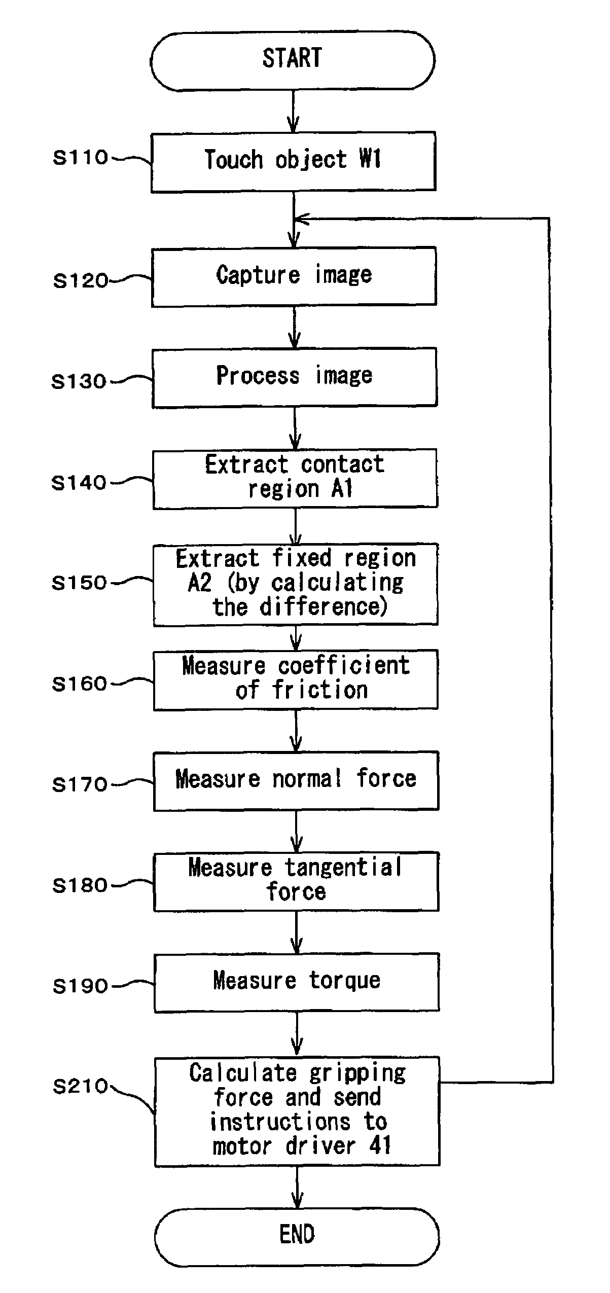
[0048]A multi-dimensional sensing system that embodies the present invention (the first embodiment) will be described in detail hereafter based on FIGS. 1 to 8.

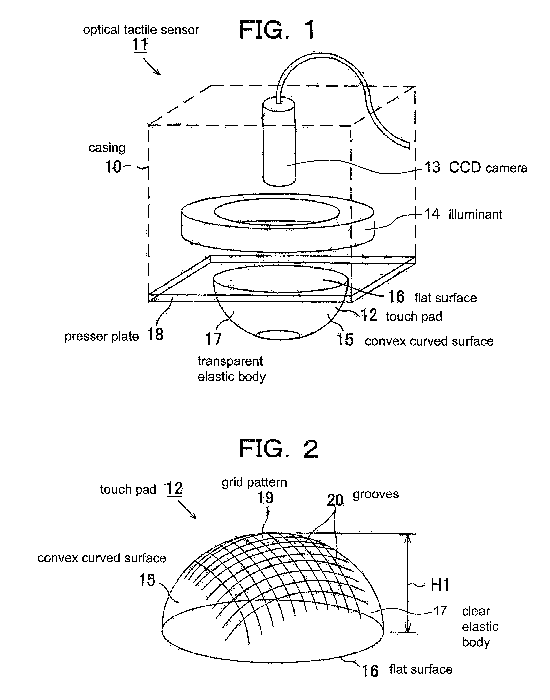
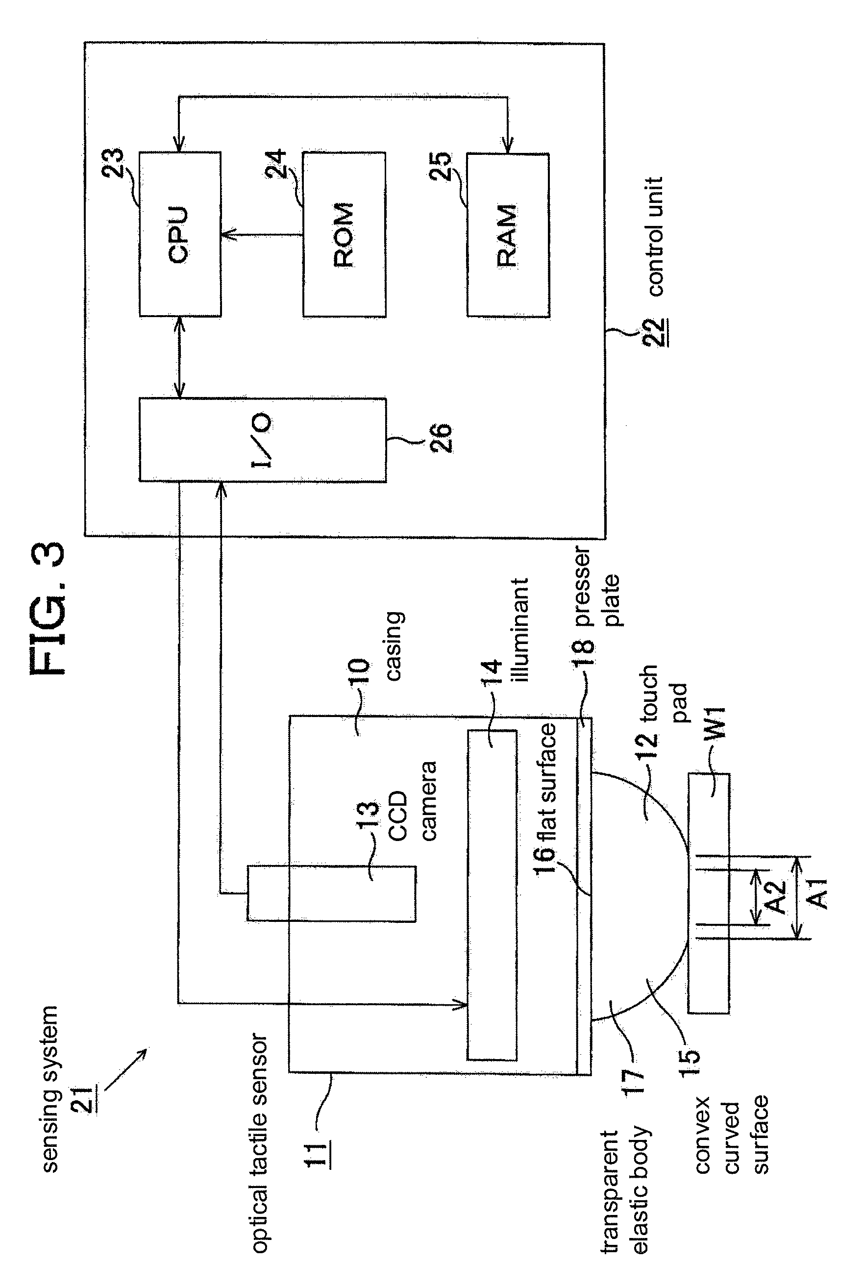
[0049]As shown in FIGS. 1 and 2, a cylindrical casing 10 encasing an optical tactile sensor 11 includes a tactile portion, such as touch pad 12 mounted on a distal end thereof. Disposed within the casing 10 is an imaging means, such as a CCD camera 13. The CCD camera 13 is disposed on the side of the touch pad 12 opposite to the side that makes contact with an object, W1 (see FIG. 3). The CCD camera 13 images the behavior (such as the displacement and deformation) of the grid pattern 19 on the touch pad 12 from behind while the object W1 is in touch with the touch pad 12. Accordingly, the CCD camera 13 is focused on the convex curved surface 15 of the touch pad 12, which bears the grid pattern 19.

[0050]Additionally disposed within the casing 10 is a circular illuminant 14 for illuminating the grid pattern 19. According to thi...

second embodiment

[0092]The second embodiment employs the first, second, and third servomotor 36 to 38 as the actuators to drive the fingers 34 and 35. Alternatively, other types of actuators, such as hydraulic cylinders, pneumatic cylinders, and ultrasonic motors, may be used instead.

[0093]An optical tactile sensor and a sensing system incorporating the optical tactile sensor according to the present invention may facilitate two-way communication of tactile information between humans and robots. For example, the present invention may be applicable to robot teaching machines which, in exemplary embodiments, teach robots subtle movements and sensitivity required of fingertips in, for example, throwing a ball.


PUM

PropertyMeasurementUnit
depthaaaaaaaaaa
depthaaaaaaaaaa
heightaaaaaaaaaa

Abstract

An optical tactile sensor has a touch pad and a CCD camera for imaging behavior of the touch pad. A CPU processes image information from the CCD camera, extracts information on the size, shape, and center of gravity of a contact region, and extracts information on the size of a fixation region. The CPU obtains a normal force from the size of the contact region, obtains a tangential force from the shape of the contact region and the center of gravity of the contact region, and obtains a friction coefficient from the ratio of the size of the fixation region to the size of the contact region.

Description

RELATED APPLICATIONS[0001]This application is a 35 U.S.C. 371 national stage filing of International Application No. PCT / JP2005 / 004259, filed 4 Mar. 2005, which claims priority to Japan Patent Application No. 2004-066401 filed on 9 Mar. 2004 in Japan. The contents of the aforementioned applications are hereby incorporated by reference.BACKGROUND OF THE INVENTION[0002]The present invention relates to optical tactile sensors, sensing methods using optical tactile sensors, sensing systems, methods and apparatuses for controlling object operating force, apparatuses for controlling object gripping force, and robot hands.[0003]Although a society where humans and humanoid robots coexist side by side is becoming more realistic, there remain a number of problems to be solved first. While improving the maneuverability and the intelligence of robots is of great importance for this purpose, improving the technology for allowing communication between humans and robots is also thought to provide ...

Claims


Application Information

Patent Timeline
Patent Type & Authority Patents(United States)
IPC IPC(8): G01L1/00G06F17/40G01L5/00B25J13/00B25J13/08B25J19/02G01L5/22G01N19/02G01V9/00
CPCB25J13/082G01N19/02G01L5/226B25J13/084
Inventor OBINATA, GOROOKA, KIYOSHIMIURA, HIROKIMORIYAMA, NOBUHIKO
Owner NAGOYA INDUSTRIAL SCIENCE RESEARCH INST
Why Eureka
Try Eureka