Device and method for determining process status by tone value and color reproduction measurement

a technology of color reproduction measurement and process status, which is applied in the direction of digitally marking record carriers, instruments, printing, etc., can solve the problem of insufficient measurement accuracy of tone value, and achieve the effect of optimizing space requirements and being made inexpensively

Inactive Publication Date: 2010-04-27
MANROLANAD AG
View PDF7 Cites 4 Cited by
  • Summary
  • Abstract
  • Description
  • Claims
  • Application Information

AI Technical Summary

Benefits of technology

[0010]Accordingly, an object of the invention is to provide possible means of determining quality-relevant parameters in the printing process as precisely as possible and with control patches arranged on the printing medium in a way that optimizes space requirements, so that the determination can be made inexpensively.
[0013]An example of a position-resolving sensor that can be used is a CCD chip. The only important consideration in the choice of a sensor is that sufficient accuracy of resolution is achieved. An accuracy of resolution of greater than 0.2 mm is regarded as especially advantageous. A central processing unit or CPU is needed to evaluate the data acquired from the position-resolving sensor. Accordingly, a PC can also be used for the data processing, but the use of a digital signal processor integrated in the measuring unit as a compact measuring instrument is preferable for the hardware realization of the measuring unit of the invention. In addition, the measuring unit also has at least one memory, which, for one thing, can temporarily store the data from the sensor and, for another, can store the computational results of the measuring device. The measuring device can be functionalized by means of a computer program, and for each printing-related measured value it also determines the position of the measuring point. If, for example, the density is determined in the gradient patch at a point by means of the measuring unit in the form of a densitometer, the measuring device is additionally able to reference the position of this point to a previously determined point. This common reference point for the measuring points is preferably the left limit, i.e., a starting point of the gradient patch. This measure, i.e., the determination of measuring point position and measured value, makes it possible to form a position-dependent series of measured values. A function can then be fitted to this series, e.g., by means of the least squares method. Printing-related information, e.g., the tone value increase (TVI) can then be derived from the function obtained in this way. In the case of the tone value increase, it is possible, for example, to obtain a more precise computation without the need for more control patches. Accordingly, the system of the invention makes it possible to obtain more precise measurement results with a smaller space requirement and thus at lower expense for the printing operation.
[0014]A refinement of the invention provides for the use of a photosensitive sensor that is position-resolving in two directions. Therefore, the measuring device determines a matrix of measured values in the vertical and horizontal directions. In order to obtain a more easily handled amount of data for further computations, the mean value of the measured values in the vertical direction is determined. The measuring device thus computes a series of values consisting of a mean value of all vertical measurements at a horizontal position. An average value that is more reliable for the evaluations is obtained by this measure. A suitable function is then approximated to the series of measured values obtained in this way to make it possible to draw conclusions about the printing process by means of a thorough analysis of this function.
[0017]Due to the fact that the control patches on the printing medium require less space, which is realized by virtue of the possibility of using gradient patches, a print control strip with smaller control patches of the printing medium in accordance with the invention can be simultaneously printed during the printing operation, which results in space and cost savings for the printing operation. The system of the invention makes it possible to realize automatic control, e.g., for metering fountain solution, by means of the measuring device, which can also be realized in the form of a computer program.
[0021]In accordance with a refinement of the method of the present invention, the position values of the measuring points are determined relative to the position of the control patch. If the entire control patch is provided with a gradient, a relationship between a position of the measuring point in the gradient and the measured value measured at the measuring point is obtained with respect to at least one limit of the control patch. This relationship can be represented in a graph by plotting the measured values over the measuring point on a Cartesian coordinate system. To be able to describe the series of measured values that has been obtained in an approximate way by a function, it is useful to perform a fit or a parameter estimate. Conclusions about the process status can then be drawn from the form of the fitted function. In the printing of a tone value gradient up to the full tone, a phase transition can be seen in the function. Starting at the phase transition, the uncovered regions between the dots become filled in, and full tone is printed. In this regard, in accordance with the present invention, it is a matter of the behavior of the function in the region of the phase transition of the fitted function, which has a steeper slope compared to the remainder of the course of the function. The phase transition represents a region in the course of the function that responds especially sensitively to specific process parameters, e.g., the metering of fountain solution. The appearance of the function in this region allows us to draw conclusions about the printing process and especially about the metering of fountain solution.

Problems solved by technology

Due to limited space, as few control patches as possible are usually printed on the prior-art print control strip.
However, the test charts known from the prior art allow only imprecise measurement of the tone value increase.

Method used


Image

  • Device and method for determining process status by tone value and color reproduction measurement
  • Device and method for determining process status by tone value and color reproduction measurement
  • Device and method for determining process status by tone value and color reproduction measurement

Examples


Embodiment Construction

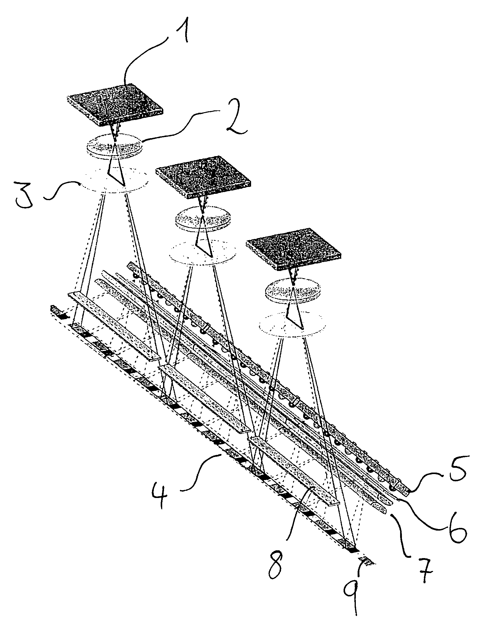
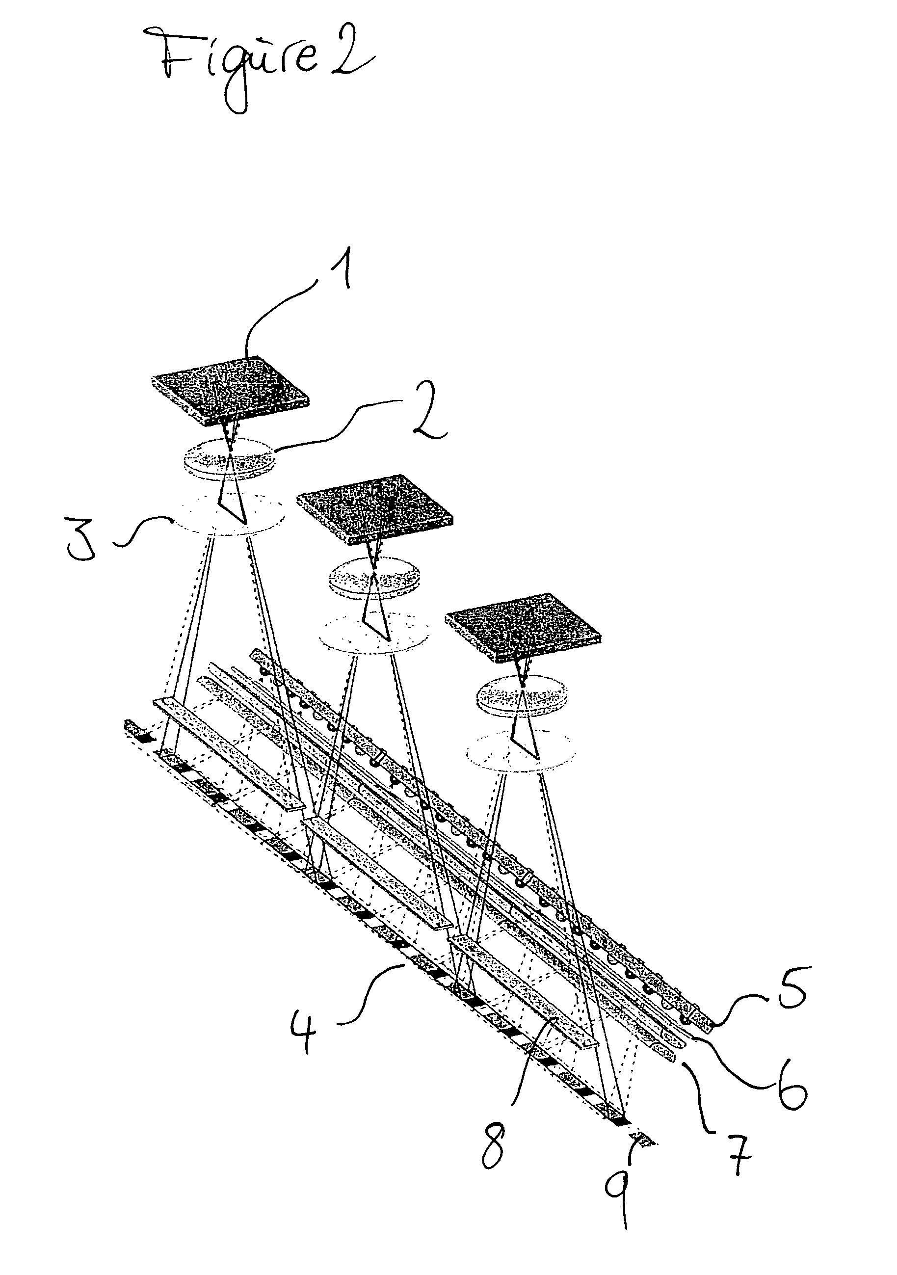
[0036]FIG. 2 shows three measuring units of the invention arranged side by side, wherein the measuring device is not shown. The illustrated components of the measuring unit of the invention are well known from the prior art and are shown only for purposes of illustration. CCD chip 1 is situated above an optical system 2 for the CCD chip. In addition, a filter 3 is located below the optical system 2. The CCD chips are positioned relative to one another in such a way that they can record the print control strip 4 with mutual overlap, wherein a black aperture array plate 8 is positioned between the filter 3 and the print control strip 4. The print control strip consists of individual control patches9, wherein no control patch with gradient is shown here. To capture the print control strip, colored LED's 5 are needed, and a filter 6 and an optical system 7 are positioned between the LED's 5 and the print control strip to be illuminated. This design is well known from the prior art and r...


PUM


Abstract

The present invention concerns measures for the space-optimized determination of printing-related measured values. With the aid of a tone value and / or color gradient in a control patch and a suitable measuring device, it is possible to obtain, in a smaller amount of space, adequate or even detailed information about the printing process. Correcting values necessary for the automatic control of the printing operation can be determined on the basis of the information thus obtained, which can be also be continuously acquired due to the space-optimized tone value and / or color gradients.

Description

BACKGROUND OF THE INVENTION[0001]1. Field of the Invention[0002]The present invention concerns a device and a method for determining printing-related measured values from a gradient patch printed as a control patch and a corresponding computer program.[0003]2. Description of the Related Art[0004]In the control of printing processes, it is necessary to determine quality-relevant parameters as often as possible in order to manage the printing process according to the determined parameters. Quality-relevant parameters are all parameters that can describe the reproduction of the subject on the medium to be printed, e.g., paper. In particular, it is important to check the reproduction of chromatic and achromatic inks. Examples of quality-relevant parameters are therefore the degree of area coverage or screen tone value that has been achieved, the tone value increase, or the full-tone density achieved with an ink. To determine these parameters, in industrial printing, e.g., in offset prin...

Claims


Application Information

Patent Timeline
Patent Type & Authority Patents(United States)
IPC IPC(8): B41F33/00
CPCB41F33/0036H04N1/6033G01N21/5911G01N21/25B41P2233/51G01N2021/5957
Inventor FEJFAR, FLORIANWEICHMANN, ARMIN
Owner MANROLANAD AG
Why Eureka
Try Eureka