
Reducing the size of a data stream produced during instruction tracing

a data stream and instruction tracing technology, applied in the field of data processing, can solve the problems of limiting the number of situations where it is useful, increasing the core frequency, and a particular problem, and achieve the effect of less evenly distributed and better compression

Active Publication Date: 2010-04-27
ARM LTD
View PDF23 Cites 90 Cited by
  • Summary
  • Abstract
  • Description
  • Claims
  • Application Information

AI Technical Summary

Benefits of technology

The present invention provides a way to monitor the behavior of a data processor by using logic to detect and analyze processing instructions. The logic includes a monitoring system that detects conditional direct branch instructions, conditional indirect branch instructions, and unconditional indirect branch instructions and designates them as marker instructions. These marker instructions help to determine the behavior of the processor when processing these instructions. By monitoring and analyzing these instructions, the system can output indicators that show the behavior of the processor, without needing to output all the data that would be needed to fully determine the program's behavior. This reduces the amount of data that needs to be output and makes it easier to analyze and troubleshoot the program. The system also includes a counter that can count the non-marker instructions that are processed after each marker instruction and output an indicator if an exception event occurs. This helps to locate the position of the exception in the program. Overall, the invention provides a more efficient and effective way to monitor and analyze the behavior of a data processor.

Problems solved by technology

Increasing core frequencies pose a particular problem for trace.
One disadvantage with XScale® is that by not outputting information on conditional branch instructions that do not execute, the indicator of a conditional branch instruction that does execute must contain sufficient information for the trace decompressor to determine which of the possible branch instructions in the instruction stream is the one that executed, which takes the form of a counter requiring many bits to encode.
In addition, because this counter counts all instructions processed that are not executed branch instructions, overflows of this counter are likely, and the trace stream therefore also has to encode overflow markers.
A second disadvantage is that it only outputs information for branch instructions, and not other conditional instructions; thus, the trace is incomplete, limiting the number of situations where it is useful.

Method used


Image

  • Reducing the size of a data stream produced during instruction tracing
  • Reducing the size of a data stream produced during instruction tracing
  • Reducing the size of a data stream produced during instruction tracing

Examples


Embodiment Construction

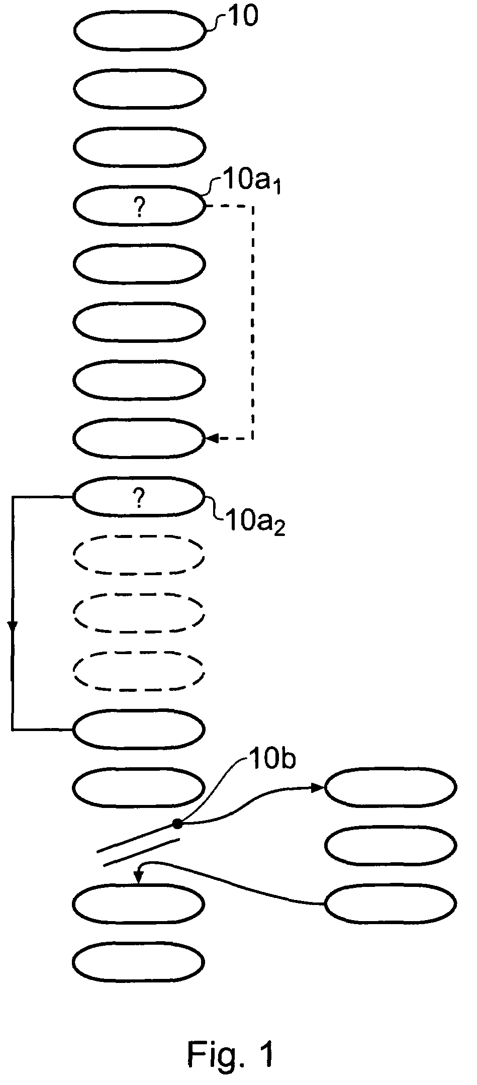
[0067]FIG. 1 shows in very simple schematic form a stream of instructions 10 being processed, the instruction stream including conditional branch instructions 10a1 and 10a2 and exception event 10b.

[0068]In this embodiment of the invention, for the instructions shown only marker instructions have information output about them. Thus in this case an N-atom is output for the non-execution of instruction 10a1 and an E-atom is output for the execution of instruction 10a2. An exception indication and a count value indicating the number of instructions to have been executed following the previous marker instruction 10a2 is output in response to exception event 10b.

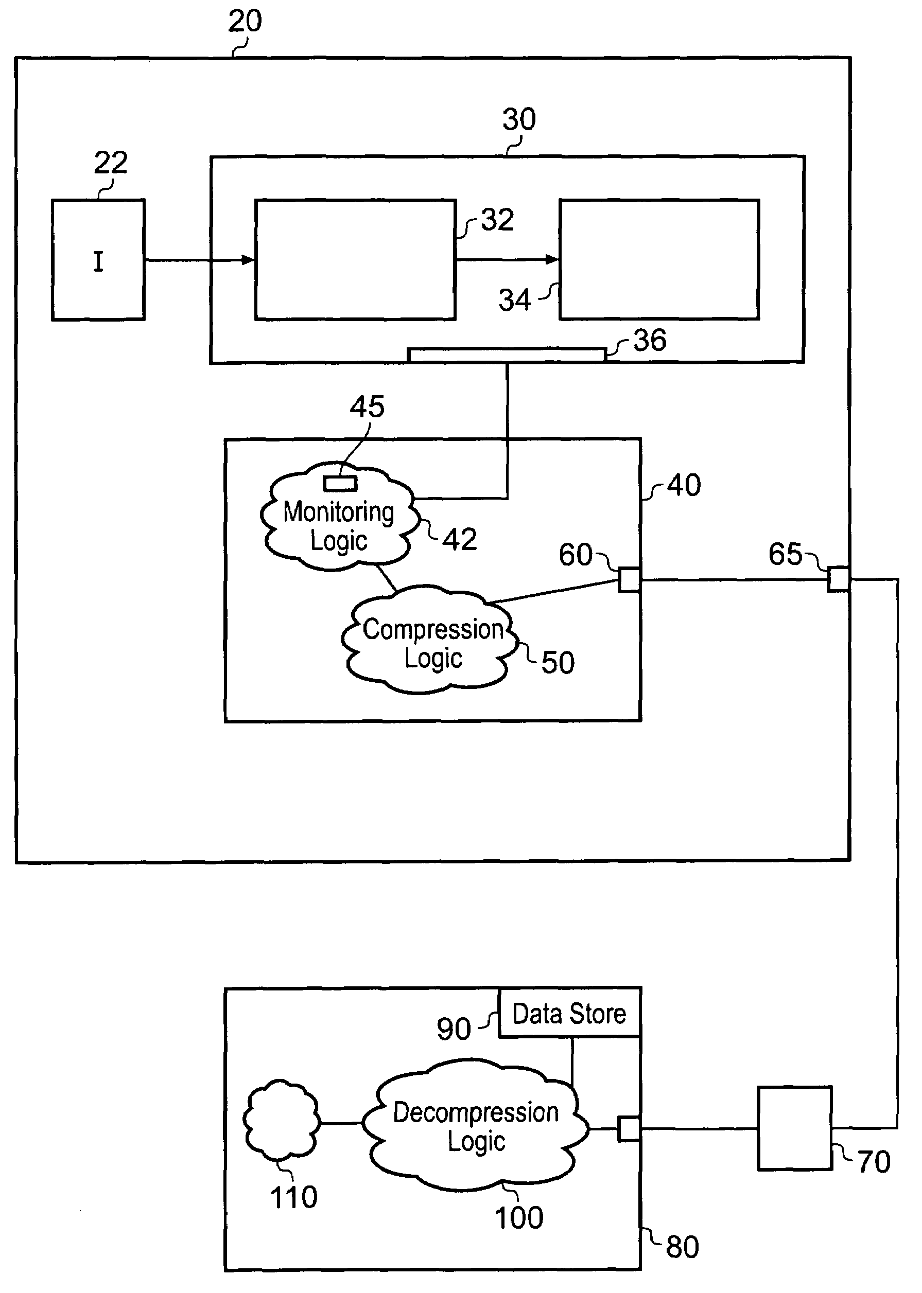
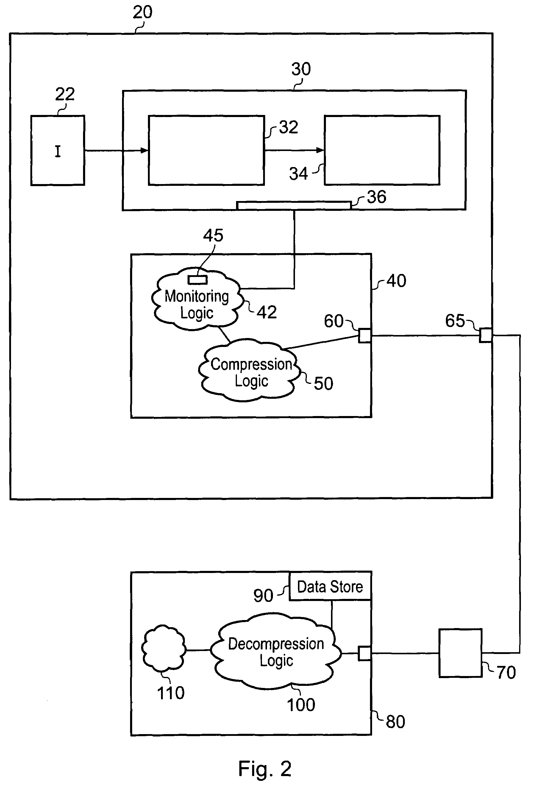
[0069]FIG. 2 shows a data processing apparatus 20 comprising a CPU 30 operable to process a program comprising an instruction stream sent from an instruction memory 22. The CPU 30 comprises an instruction fetch unit 32, a pipeline 34 and a trace interface 36. The data processing apparatus also comprises an Embedded Trace Macroce...


PUM


Abstract

Tracing logic for monitoring a stream of processing instructions from a program being processed by a data processor is disclosed, said tracing logic comprising monitoring logic operable to detect processing of said instructions in said instruction stream; detect which of said instructions in said instruction stream are conditional direct branch instructions, which of said instructions in said instruction stream are conditional indirect branch instructions and which of said instructions in said instruction stream are unconditional indirect branch instructions; said tracing logic further comprising compression logic operable to: designate said conditional direct branch instructions, said conditional indirect branch instructions and said indirect branch instructions as marker instructions; for each marker instruction, output an execution indicator indicating if said marker instruction has executed or a non-execution indicator indicating if said marker instruction has not executed and not output data relating to previously processed instructions that are not marker instructions.

Description

CROSS REFERENCE TO RELATED APPLICATIONS[0001]Related co-pending U.S. patent application Ser. No. 11 / 442,594, filed May 30, 2006, Williams et al, is commonly owned and herein incorporated by reference.BACKGROUND OF THE INVENTION[0002]1. Field of the Invention[0003]The field of the invention relates to data processing and in particular to diagnostic mechanisms for monitoring data processing operations.[0004]2. Description of the Prior Art[0005]There are a number of situations where it is desirable to keep track of the processing being performed by a processing circuit, and in such situations it may be desirable to be able to identify an order that instructions are processed in and to determine at any point in time which instruction is being processed. For example, such information is useful during the development of data processing systems, where it is often desirable to track the activity of the processing circuit. An example of a tool that may be used to assist in such a process is ...

Claims


Application Information

Patent Timeline
Patent Type & Authority Patents(United States)
IPC IPC(8): G06F11/36
CPCG06F9/3804G06F9/3844G06F11/348G06F11/3636G06F11/3447Y02B60/165G06F2201/88G06F11/3471G06F9/322G06F9/30061Y02D10/00G06F9/30054G06F9/323
Inventor ASHFIELD, EDMOND JOHN SIMONWILLIAMS, MICHAEL JOHNHORLEY, JOHN MICHAELGRISENTHWAITE, RICHARD ROY
Owner ARM LTD
Learn More