Ambidextrous charging handle for firearm

a charging handle and firearm technology, applied in the field of firearms charging handles, can solve the problems of inefficiency of triangular plan form, never been easy, sure, or efficient for left-handed operators, and difficult to charge or off-side firearms, etc., to improve the tactile gripping surface and grip or grasp the charging handle more positively.

Inactive Publication Date: 2010-05-04
HOEL THOMAS TRAIL
View PDF7 Cites 62 Cited by
  • Summary
  • Abstract
  • Description
  • Claims
  • Application Information

AI Technical Summary

Benefits of technology

[0017]A second unique improvement is to provide an ambidextrous charging handle that may be used without any separate manual operation of the latch mechanism. This is achieved through the use of the latch mechanism being activated by the simple act of pulling the handle in a rearward motion, and the previous method of initially and separately squeezing the latch is no longer necessary or required.
[0018]A third unique improvement is the provision of an ambidextrous charging handle that uses cam activation of the latch mechanism to eliminate the manual squeezing of the latch. This is achieved through the use of two separate connector points. These provide firstly a combined firearm receiver retention and pivot function to the latch and the central shaft and secondly, another combined retention and pivot function to the latch that also interfaces with a relief cut in the latch, thus providing a camming activation, retention and pivot function with respect to the grasping handle. This combination of retention and pivot connectors allows the rearward movement of the handle assembly to initially transmit the retraction force to the latch, opening the latch just prior to the time that the rearward force applied to the central shaft results in retraction of the firearm's bolt carrier and / or bolt. This is achieved through the interaction between the second retention and pivot function and the relief cut in the latch that converts the retraction motion of the connector into a lateral movement of the latch body in a calculated angular translation of motion.
[0019]A fourth unique improvement is the provision of an ambidextrous charging handle that provides for an improved tactile gripping surface, allowing the user to grip or grasp the charging handle more positively though the addition of tactile serrations, raised or lowered edges, ridges, bumps or flanges to the handle assembly.

Problems solved by technology

The irregular geometric shape of this early design when grasped to open the latch, combined with the physically small triangular surfaces available made rapid or off-side charging of the firearm extremely difficult, if not entirely impossible under certain operational conditions.
The entire series of these charging handles in the art was designed solely around right-handed operators and has never been easy, sure, or efficient for left-handed operators to function, or even right-handed operators using the handle in the off-side, or slung positions.
When it was realized that the original triangular plan form was inefficient and difficult to use the charging handle's external grasping surface shape was redesigned.
Despite the standardization of this later design, little has been done in the ensuing years to improve upon the inherent problems and defects of effective grasping of the less than ideal shape of the handle, combined with the need to manually function the left side receiver retention latch, exclusively.
This was already a significant enough difficulty for right-handed operators of the firearm system but when left handed or even off-side charging was contemplated, the tactile problems become nearly insurmountable, thus contributing significantly to the operator's loss of effectiveness or rapidity in charging the firearm, especially under immediate action requirements, such as during military combat or police enforcement operations.

Method used


Image

  • Ambidextrous charging handle for firearm
  • Ambidextrous charging handle for firearm
  • Ambidextrous charging handle for firearm

Examples


Embodiment Construction

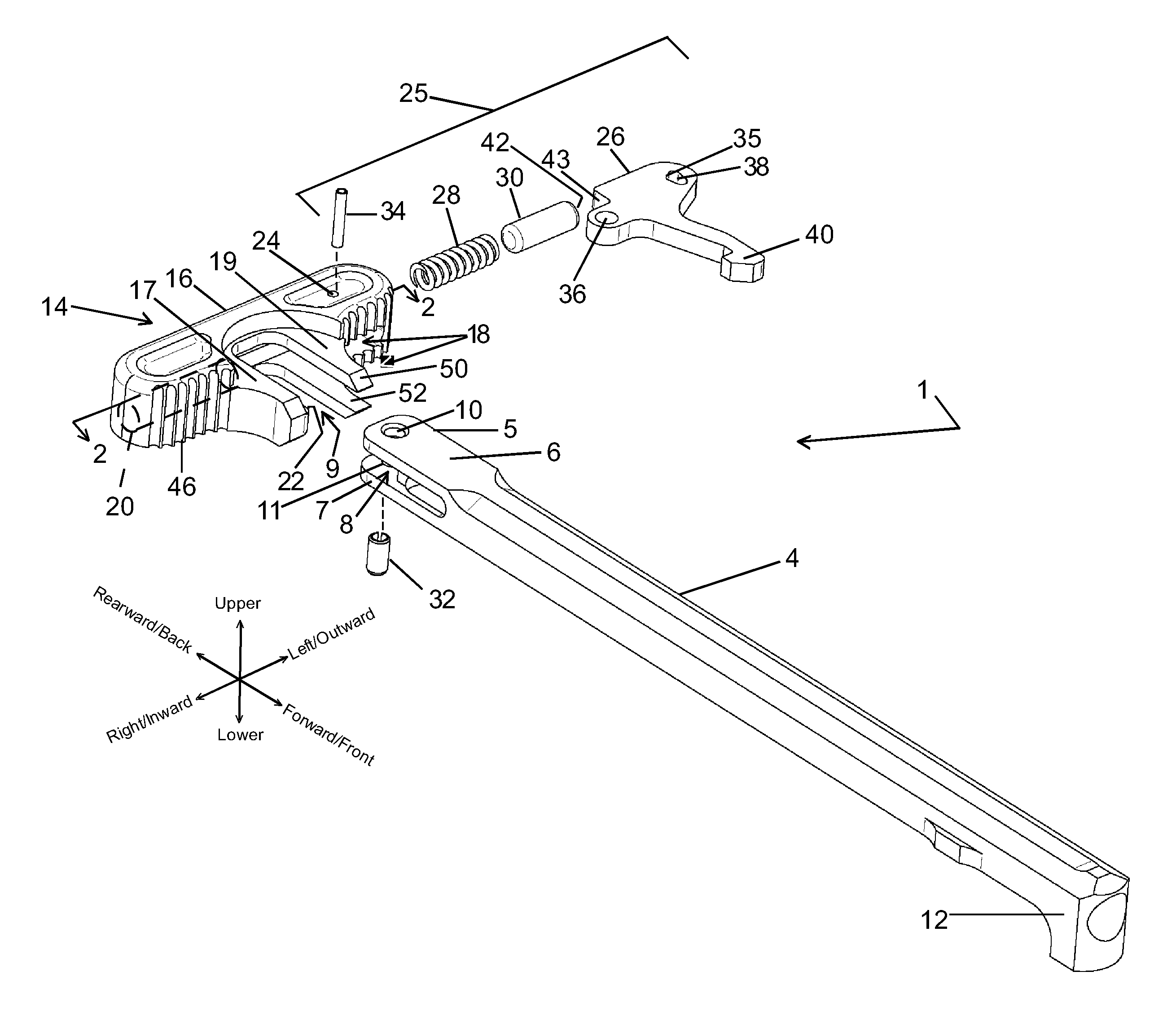
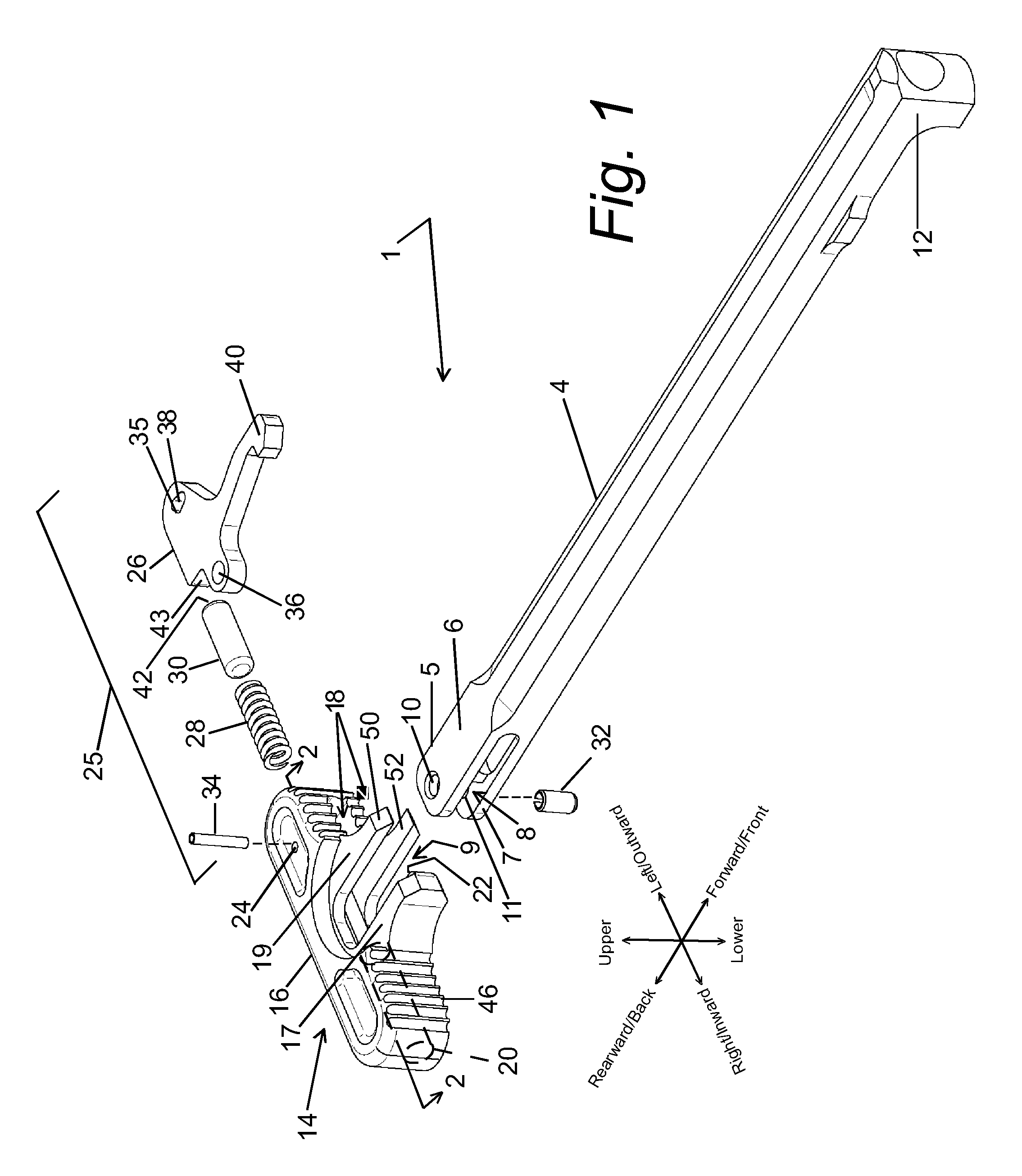
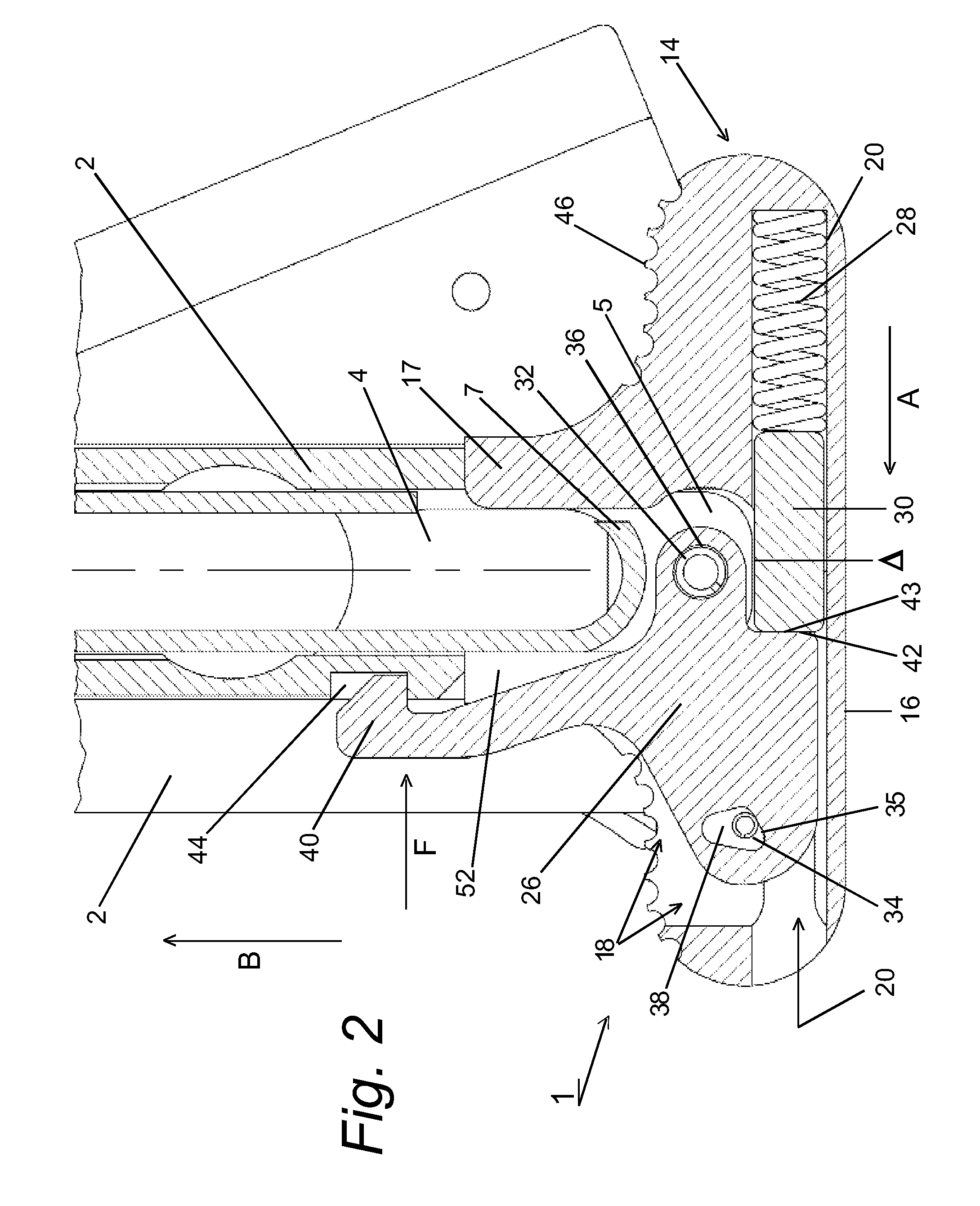
[0026]Referring in detail to FIG. 1 an ambidextrous charging handle 1 consists of central shaft 4, oblong handle 14, and latch assembly 25 that consists of latch 26, spring 28, biasing pin 30, and major and minor pivot connectors 32, 34. The central shaft 4 comprises an elongated portion terminating in body 6 having a transverse horizontal slot 8 machined through the body at the proximal end of the central shaft to form upper and lower tangs 5, 7. At the proximal end of the central shaft a vertical bore hole 10 is located through both upper and lower tangs 5, 7 of the body 6. At a distal end of the central shaft 4 a bolt hook is provided to engage a bolt carrier (not shown) located within upper receiver 2, as seen in FIG. 2. The oblong handle 14 has a cross bar section 16, a horizontal slot 18 machined partially therethrough and a cylindrical bore recess 20 that extends horizontally through the left hand side of the oblong handle and terminates within the right hand side of the oblo...


PUM


Abstract

An ambidextrous charging handle for a Stoner-type firearm. The charging handle comprises two separate assemblies, these being an oblong handle that contains a latch assembly and a central shaft member. The parts are joined together by a compound pivoting arrangement in which a combination of the latch assembly and alignment grooves in the central shaft member interacting with slidingly engage a locating flange on the oblong handle, and a pair of pivoting connectors that secure the latch assembly to the oblong handle and the central shaft member independently from one another. The latch assembly includes cam activation via a retention relief cut acting against a fixed minor pivot connector. The second point of retention for the assembly is via a major pivoting connector the combination of which transmits the retraction force applied to the oblong handle on one end of the latch assembly and to the central shaft member through the interconnection of the minor pivot connector located at the proximal end of the latch body.

Description

BACKGROUND OF THE INVENTION[0001]1. Field of the Invention[0002]This application relates broadly to ambidextrous charging handles for firearms. More particularly, it concerns an improved form of an ambidextrous charging handle for military and semi-automatic firearms, particularly the Stoner-type firearm systems including the AR-10, AR-15, M16, M4 series and all subsequent AR-10 type, AR-15 type, M16 type, M4 type firearms, their clones, and derivatives.[0003]2. Description of the Prior Art[0004]Charging handles for this type of firearm system have been described since the very first version of Eugene Stoner's original firearm design universally first known as the AR-15 type rifle, and later adopted by various militaries as the “M16” series.[0005]There were several iterations of the basic charging handle designed, tested, and proposed for military adoption, and later on for commercial sales. The earliest Stoner-inspired design had a semi-triangular shape where the base of the triang...

Claims


Application Information

Patent Timeline
Patent Type & Authority Patents(United States)
IPC IPC(8): F41A7/02
CPCF41A35/06F41A3/20F41A3/72
Inventor HOEL, THOMAS TRAIL
Owner HOEL THOMAS TRAIL
Why Eureka
Try Eureka