This helps you quickly interpret patents by identifying the three key elements:
Problems solved by technology
Method used
Benefits of technology
Benefits of technology
[0011]The present invention takes into consideration the above situation with the object of providing a fuel cell vehicle system which can improve the energy efficiency of a fuel cell vehicle during regeneration by the propulsion motor.
[0014]On the other hand, when the chargeable power is less than the regenerative electric power, the output current of the fuel cell is restricted, to thereby prevent the energy storage device being over charged by the power generation of the fuel cell, and thus enable the energy efficiency of the fuel cell vehicle during regenerative operation of the propulsion motor to be improved.
[0016]According to the fuel cell vehicle system of the above configuration, in the case where the chargeable power which can be charged to the energy storage device is greater than the regenerative electric power which can be generated by the regenerative operation of the propulsion motor, the restriction on the output current of the fuel cell is cancelled, so that the energy storage device can be promptly charged by the power generation of the fuel cell and by the regenerative operation of the propulsion motor. Furthermore, in the case where the pressure of the reactant gas at the fuel electrode of the fuel cell is greater than the predetermined pressure, even though the chargeable output power is less than the regenerative output power, the restriction on the output current of the fuel cell is cancelled, and reactant gas is supplied to the oxygen electrode by means of a power generation command corresponding to the pressure of the reactant gas at the fuel electrode. Moreover, by continuing the power generation, the electrode gap differential pressure due to the reactant gas between the fuel electrode and the oxygen electrode of the fuel cell can be prevented from increasing excessively.
[0017]On the other hand, when the chargeable power is less than the regenerative electric power and the pressure of the reactant gas at the fuel electrode of the fuel cell is less than a predetermined pressure, supply of the reactant gas to the oxygen electrode of the fuel cell is stopped, and the output current of the fuel cell is restricted. As a result, excessive charging of the energy storage device due to the power generation of the fuel cell can be prevented, and the energy efficiency of the fuel cell vehicle at the time of regenerative operation of the propulsion motor can be improved. Furthermore, by restricting the output current by means of the output control device, a situation where power generation stops due to the pressure of the reactant gas at the fuel electrode becoming less than the predetermined pressure, or an excessive current is extracted from the restricted fuel cell, can be prevented, so that the fuel cell can be maintained in an appropriate condition.
Problems solved by technology
However, in the case where during regeneration of the propulsion motor, the power generation of the fuel cell continues, and for example the regenerative electric power of the propulsion motor is greater than the chargeable power which can be charged to the energy storage device, there is the possibility that unnecessary power generation continues, so that the energy efficiency of the fuel cell vehicle drops.
Method used
Image
Click on the blue label to locate the original text in one second.
Reading with bidirectional positioning of images and text.
Examples
first embodiment
[0028]The following describes a fuel cell vehicle system according to the present invention, with reference to the appended drawings.
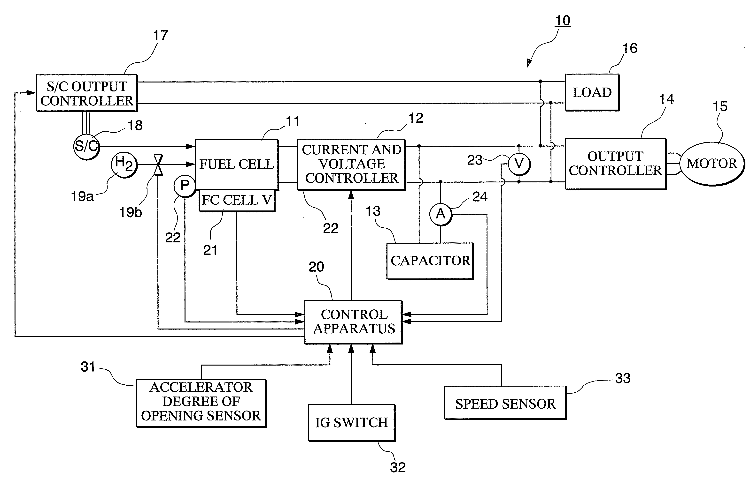
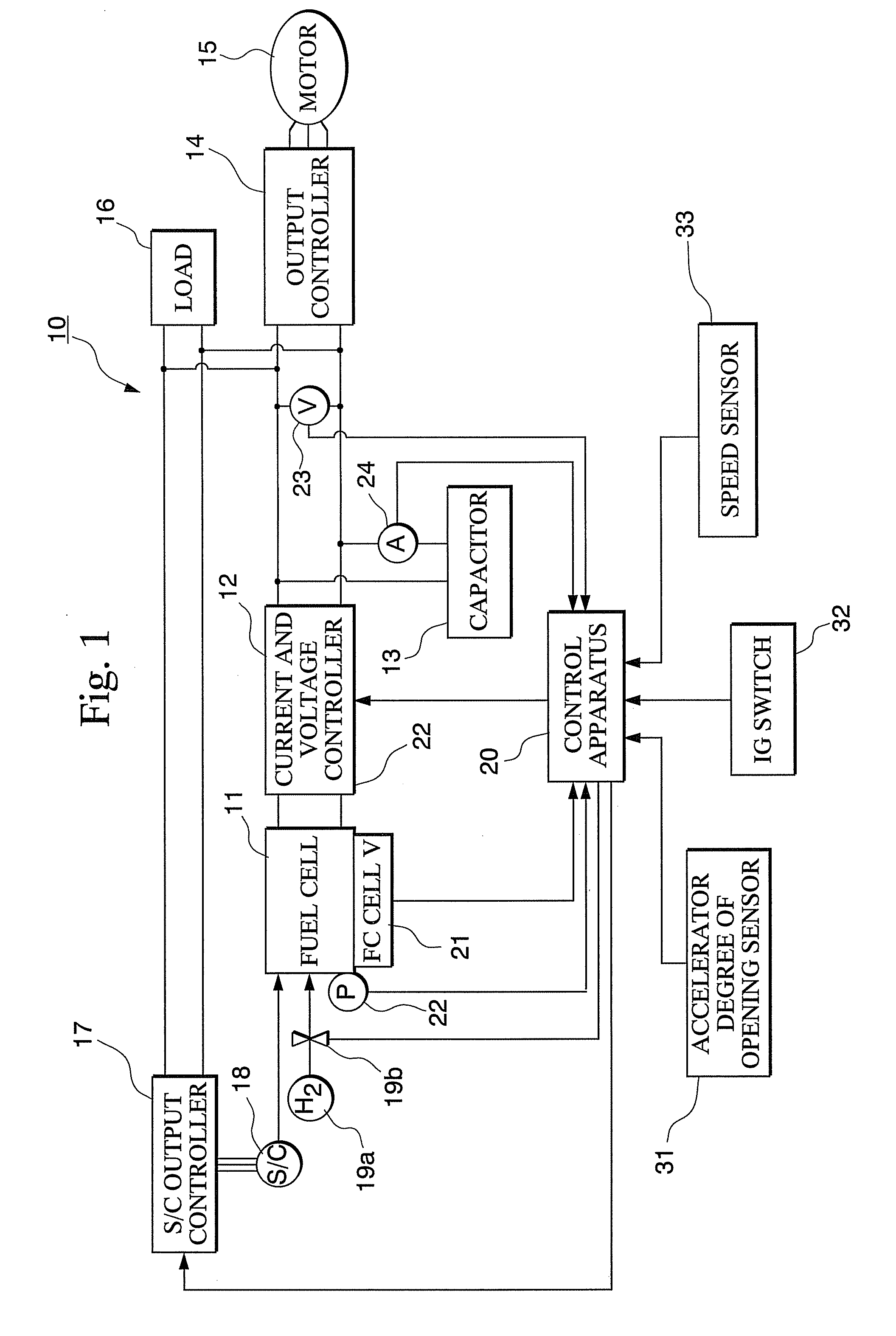
[0029]A fuel cell vehicle system 10 according to the first embodiment includes for example as shown in FIG. 1; a fuel cell 11, a current and voltage controller 12, a capacitor 13, an output controller 14, a propulsion motor 15, a load 16, an S / C output controller 17, an air compressor (S / C) 18, a hydrogen tank 19a and hydrogen supply valve 19b, a control apparatus 20, a fuel cell unit voltage sensor 21, an anodevoltage sensor 22, a capacitorvoltage sensor 23, a capacitorcurrent sensor 24, a degree of opening of the accelerator sensor 31, an IG switch 32, and a speed sensor 33.
[0030]The fuel cell 11 includes a stack of fuel cell units made up with an electrolyte electrode structure holding a solidpolymerelectrolyte membrane formed from a positive ion exchange membrane or the like sandwiched between a fuel electrode (anode) formed from an anode cata...
second embodiment
[0088]The fuel cell vehicle system 110 has the aforementioned configuration. Next is a description of the operation of the fuel cell vehicle system 110, in particular the operation during travelling of the fuel cell vehicle, with reference to the appended drawings.
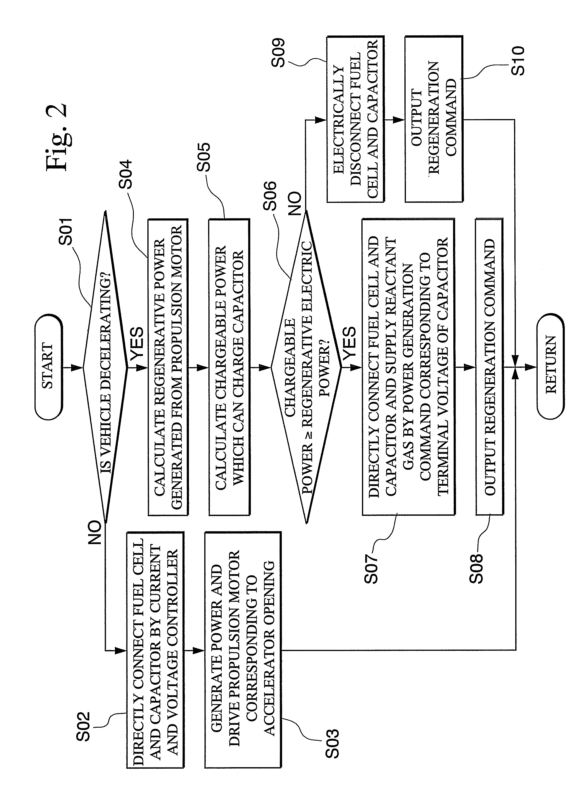
[0089]At first, in step S01 of FIG. 5, it is determined whether or not the fuel cell vehicle is decelerating, according to for example a time change of the opening of the accelerator related to the accelerator operation amount of the driver, or for example the direction of the current being charged to the battery 13A, that is whether this is a charging current or a discharge current, or the like.
[0090]If the determination result is YES, the flow proceeds to the next step S04.
[0091]On the other hand if the determination result is NO, the flow proceeds to step S02A.
[0092]In step S02A, the duty ratio of the control pulse input to current and voltage controller 12 is set to 100%, and the fuel cell 11 and the battery 13A are s...
third embodiment
[0126]The fuel cell vehicle system 210 has the aforementioned configuration. Next is a description of the operation of the fuel cell vehicle system 210, in particular the operation during travelling of the fuel cell vehicle, with reference to the appended drawings.
[0127]At first, in step S01 of FIG. 8, it is determined whether or not the fuel cell vehicle is decelerating, according to for example a time change of the opening of the accelerator related to the accelerator operation amount of the driver, or for example the direction of the current being charged to the battery 13A, that is whether this is a charging current or a discharge current, or the like.
[0128]If the determination result is YES, the flow proceeds to the next step S04.
[0129]On the other hand if the determination result is NO, the flow proceeds to step S02B.
[0130]In step S02B, the duty ratio of the DC-DC-converter 40 is set to 100% so that electric current from the fuel cell 11 to the battery 13A is not restricted.
[...
PUM
Abstract
A fuel cell vehicle system includes: a propulsion motor capable of driving a vehicle; a fuel cell which generates electric power by supplying a reactant gas to give an electrochemical reaction; an energy storage device which is charged by a generated output of the fuel cell and regenerative electric power of the propulsion motor; an output control device which controls an output current of the fuel cell; and a control device which calculates the regenerative electric power which can be generated by a regenerative operation of the propulsion motor as well as a chargeable power which can be charged to the energy storage device, controls the output control device so that the output current of the fuel cell is restricted when the chargeable power is less than the regenerative electric power, and controls the output control device so that restriction on the output current of the fuel cell is canceled when the chargeable power is equal to or greater than the regenerative electric power.
Description
CROSS REFERENCE TO RELATED APPLICATIONS[0001]This is a Continuation-in-Part application of U.S. patent application Ser. No. 11 / 648,212, filed Dec. 29, 2006, which is a Continuation application of U.S. patent application Ser. No. 10 / 723,942, filed Nov. 26, 2003 and claiming priority on Japanese Patent Application No. 2002-347148, filed Nov. 29, 2002, the contents of aforementioned applications are entirely incorporated herein by reference.BACKGROUND OF THE INVENTION[0002]1. Field of the Invention[0003]The present invention relates to a fuel cell vehicle system.[0004]2. Description of the Related Art[0005]A solidpolymer membrane fuel cell conventionally includes, for example, cells formed by sandwiching a solidpolymerelectrolyte membrane between a fuel electrode (anode) and an oxygenelectrode (cathode), with a plurality of such cells arranged in a stack. Hydrogen is supplied to the fuel electrode as fuel, and air is supplied to the oxygen electrode as oxidant, and hydrogen ions ge...
Claims
Application Information
Patent Timeline
Application Date:The date an application was filed.
Publication Date:The date a patent or application was officially published.
First Publication Date:The earliest publication date of a patent with the same application number.
Issue Date:Publication date of the patent grant document.
PCT Entry Date:The Entry date of PCT National Phase.
Estimated Expiry Date:The statutory expiry date of a patent right according to the Patent Law, and it is the longest term of protection that the patent right can achieve without the termination of the patent right due to other reasons(Term extension factor has been taken into account ).
Invalid Date:Actual expiry date is based on effective date or publication date of legal transaction data of invalid patent.

