Solid product dispenser

a dispenser and solid product technology, applied in the direction of dissolving, liquid displacement, separation process, etc., can solve problems such as foaming

Inactive Publication Date: 2010-05-04
ECOLAB USA INC
View PDF6 Cites 11 Cited by
  • Summary
  • Abstract
  • Description
  • Claims
  • Application Information

AI Technical Summary

Problems solved by technology

Still further, when the additional diluent is added to the use solution, in prior art dispensers, there is often a problem of foaming.

Method used


Image

  • Solid product dispenser
  • Solid product dispenser
  • Solid product dispenser

Examples


Embodiment Construction

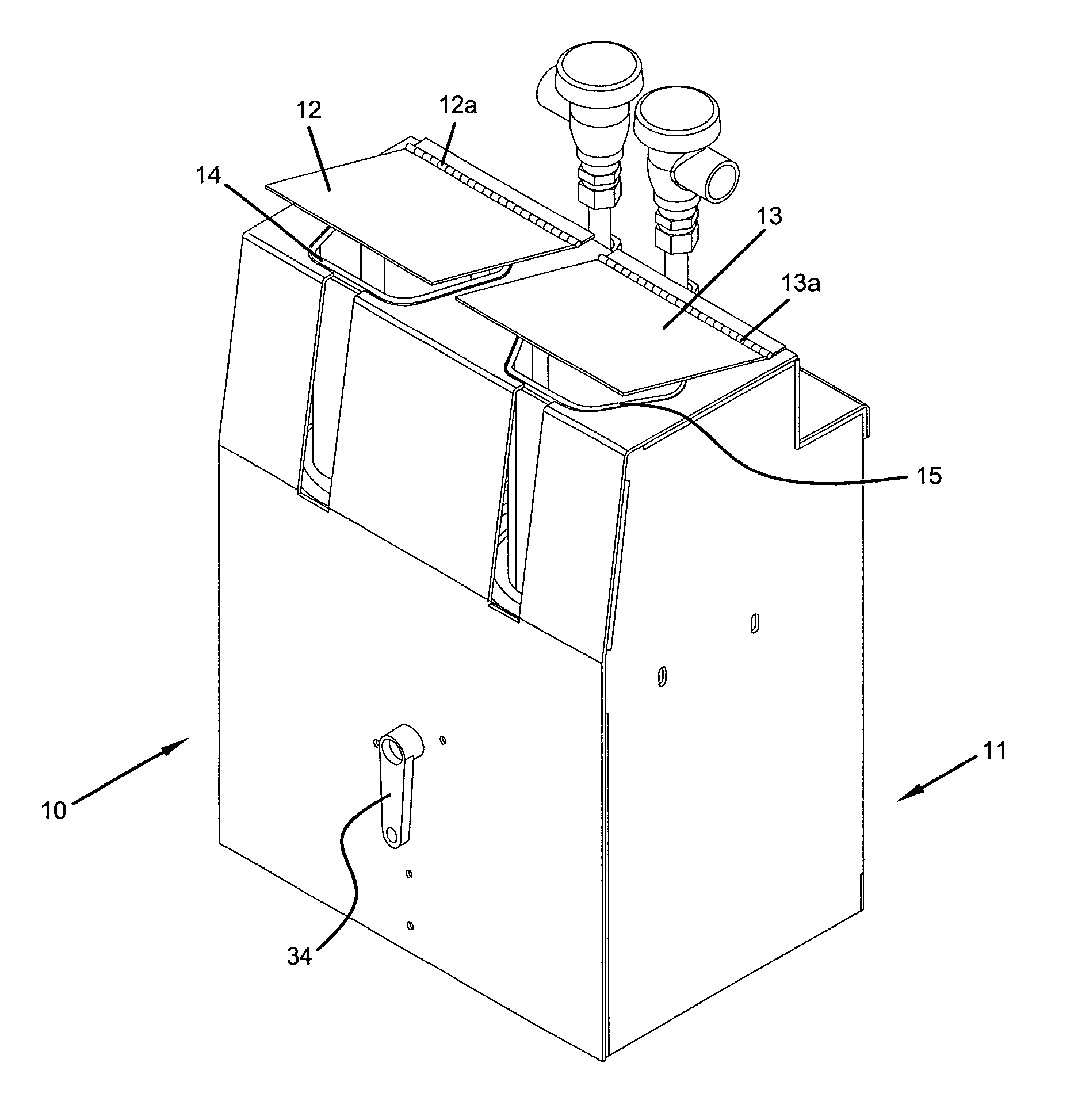
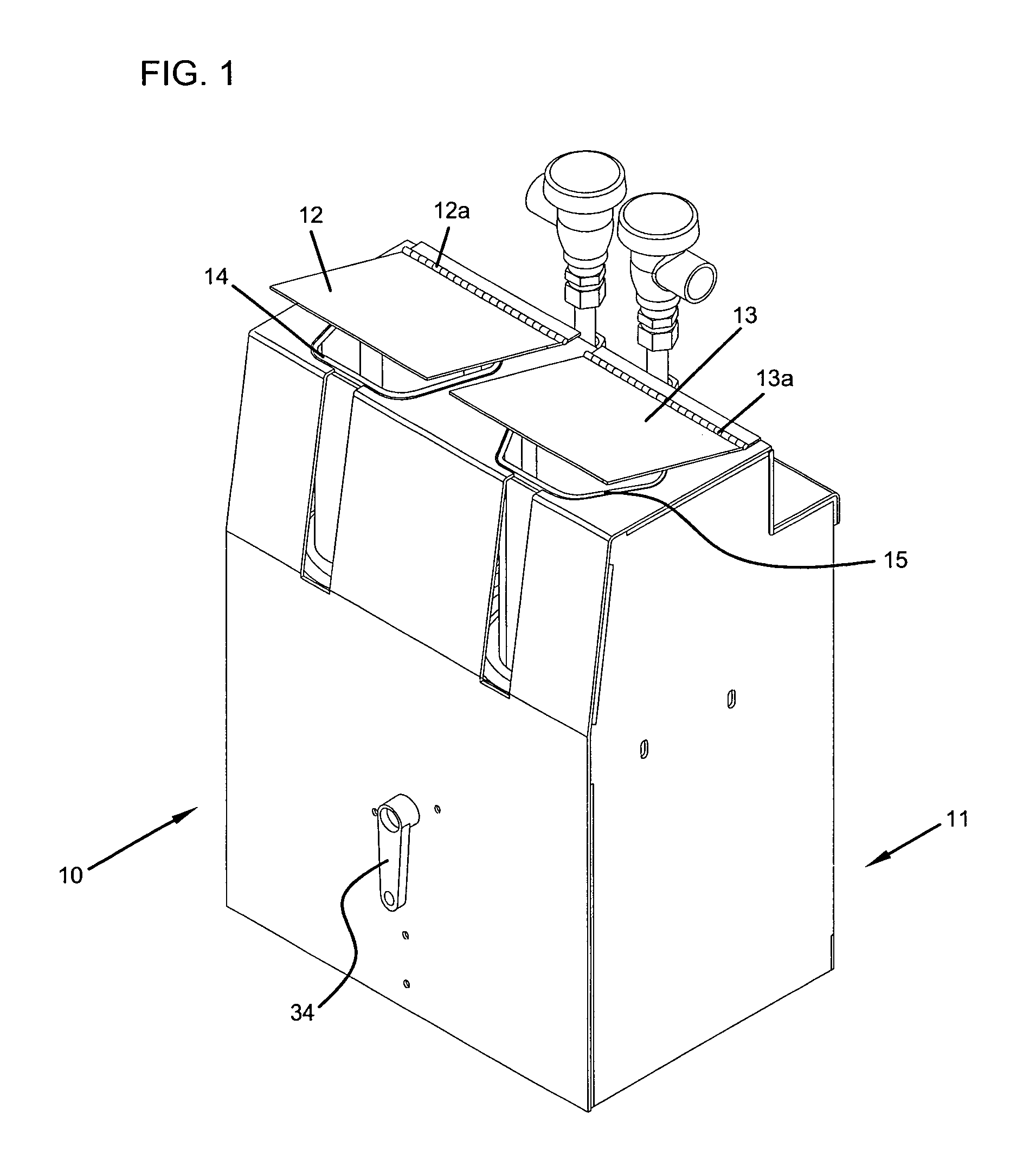
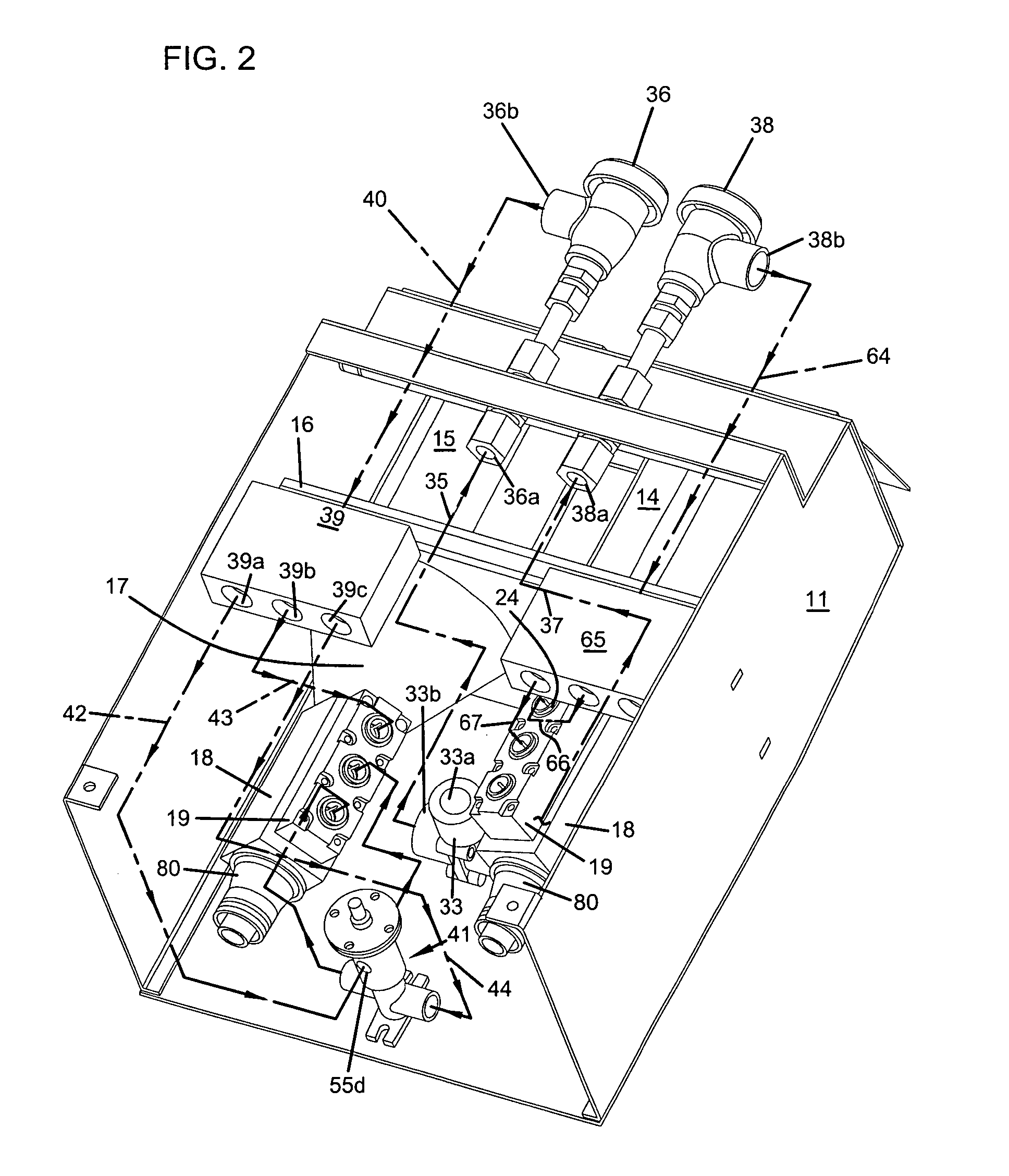
[0023]Referring to the drawing, wherein like numerals represent like parts throughout the several views, there is generally disclosed at 10 a dispenser. The dispenser 10 includes a housing 11. The housing 11 has two lids 12, 13 operatively connected to the housing 11 by suitable means such as a hinges 13, 14a. The housing 11 encircles the dispenser 10. However, as shown in FIG. 2, the back and bottom have been removed for clarity. The housing 11 has an inner cavity 1 lain which two product holders 14, 15 are positioned. The product holders 14, 15 are for receiving a suitable solid product such as a detergent, sanitizer or other suitable chemicals from which it is desired to make a use solution. Dispenser 10 is shown as having two product holders 14, 15. However, it is understood that either a single product holder or more product holders may also be incorporated in a dispenser 10 that utilizes the present invention. The dispenser 10 has a screen 16 that extends across the cavity 11a...


PUM

PropertyMeasurementUnit
pressureaaaaaaaaaa
pressuresaaaaaaaaaa
pressureaaaaaaaaaa

Abstract

A dispenser (10) uses first and second flow controls (70, 73). The flow controls maintain first and second flow ranges independent of diluent pressure within a pressure range, wherein the use solution's concentration is maintained over the pressure range. A third flow control (75) may also be utilized in a third diluent passageway for maintaining a third flow range independent of the diluent pressure within the pressure range. A bypass valve assembly (41) is operatively connected to the third incoming diluent passageway. The bypass valve has a temperature control valve. The temperature control valve having a bypass passageway, wherein additional diluent is added to the use solution, thereby controlling the use solution's concentration.

Description

[0001]This application claims priority to U.S. Provisional Patent Application No. 60 / 619,783, filed Oct. 18, 2004.BACKGROUND OF THE INVENTION[0002]1. Field of the Invention[0003]This invention relates generally to the invention of dispensing a solid product with a diluent, and more particularly to a method and apparatus of controlling the dispensing rate when the diluent changes temperature.[0004]2. Description of the Prior Art[0005]Dispensers that utilize a diluent to erode a product, such as a sanitizer or detergent, are well known. The product being dispensed is typically a solid product and can take the form of either a solid block of chemicals, pellets or a cast product. One example of such a dispenser is found in U.S. Pat. No. 4,826,661 by Copeland et al. This patent discloses a solid block chemical dispenser for cleaning systems. The dispenser includes a spray nozzle for directing a uniform dissolving spray on to a surface of a solid block of cleaning composition. The nozzle ...

Claims


Application Information

Patent Timeline
Patent Type & Authority Patents(United States)
IPC IPC(8): B01D11/02
CPCA47L15/4436B01F1/0027B01F15/00344B01F15/00123B01F5/02Y10T137/4891Y10T137/0396B01F21/4021B01F21/221B01F21/22B01F25/20B01F35/20B01F35/2115B01F35/2211B01F35/718051
Inventor THOMAS, JOHN E.PLANTIKOW, ROBERT J.BERG, THOMAS P.BATCHER, THOMASBRADY, DANIEL F.RUSSELL, SCOTT T.EVERSON, TERRENCE P.
Owner ECOLAB USA INC
Why Eureka
Try Eureka