Independent reference pulse generation

a reference pulse and reference technology, applied in the field of fill level measuring, can solve problems such as overload effects in sampling mixers

Active Publication Date: 2010-05-04
VEGA GRIESHABER GMBH & CO
View PDF13 Cites 9 Cited by
  • Summary
  • Abstract
  • Description
  • Claims
  • Application Information

AI Technical Summary

Benefits of technology

[0012]Furthermore, the reference pulse may be independent of reflections that can arise between the transmitter-receiver filter circuit and the antenna. Moreover, the reference pulse may be independent of large echoes at short range, which echoes may result in overload effects in the sampling mixer. There may be no need to provide a delay line on the transmission frequency of the radar sensor, which delay line, due to the large attenuation, may require a transmission amplifier.
[0021]Another option consists of using two separate analog-digital converters which one after another write their digitalised values to a memory. In this arrangement the first analog-digital converter only samples the reference pulse, while the second analog-digital converter only samples the echo signals. In this way changing over the intermediate-frequency signals may not have to be performed.
[0025]In addition or as an alternative to the adjustable attenuation device, this first amplifier can be inserted between the filter and the directional coupler, or between the coupler and the transmitter-receiver filter circuit. This may make it possible to effectively vary the transmitting power in order to prevent overload in the case of reflective media and / or at short range.
[0029]This may result in a simple design of the sampling mixer and of the intermediate-frequency amplifier.
[0033]According to a further exemplary embodiment of the present invention, the delay device is designed as a simple line in a multilayer printed circuit board. Such a delay line may be manufactured in a simple manner.
[0040]In this way a method may be provided, by way of which interference to the reference pulse may be effectively reduced.

Problems solved by technology

Moreover, the reference pulse may be independent of large echoes at short range, which echoes may result in overload effects in the sampling mixer.

Method used


Image

  • Independent reference pulse generation
  • Independent reference pulse generation
  • Independent reference pulse generation

Examples


Embodiment Construction

[0053]The views in the figures are diagrammatic and not to scale.

[0054]In the following description of the figures the same reference characters are used for identical or similar elements.

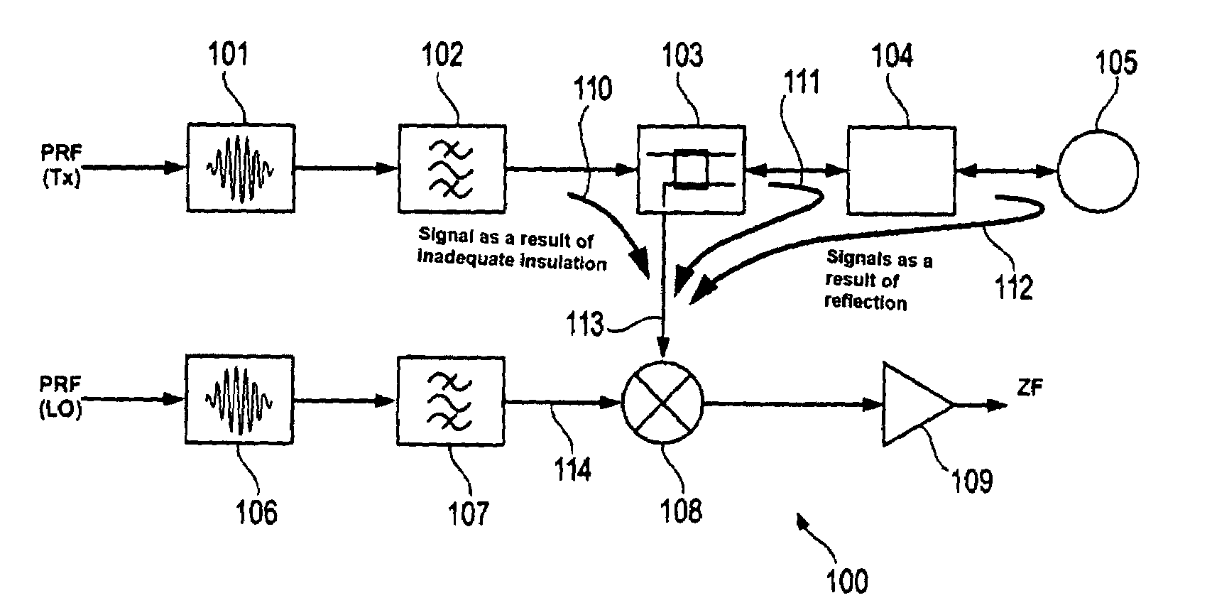
[0055]FIG. 1 shows a block diagram of a microwave module 100 with the reflections 110, 111, 112 which arise therein and which together form the reference pulse.

[0056]The microwave module 100 comprises an oscillator or pulse generator 101 for generating a transmission signal which subsequently passes through the filter 102. Furthermore, a transmitter-receiver filter circuit 103 is provided through which the transmission signal passes. Subsequently the transmission signal reaches the transition 104 between the microstrip and the coaxial line and then reaches the waveguide coupling 105 that leads to the antenna (not shown in FIG. 1).

[0057]The transmission signal is then emitted from the antenna, is reflected from the product contained in the container, and is received by the antenna. Said transmission...


PUM


Abstract

In fill-level measuring devices according to the pulse-transit-time method, a reflection that is generated internally in a microwave module is used as a reference for transit time measuring. For generating the reference pulse, the microwave module comprises its own sampling mixer or its own oscillator. Subsequently, the echo signal and the reference pulse can be further processed separately or together. No delay line is necessary on the transmission frequency of the radar sensor. Interference as a result of leakage signals is largely prevented.

Description

REFERENCE TO RELATED APPLICATIONS[0001]This application claims the benefit of the filing date of DE Patent Application Serial No. 10 2006 034 554.1 filed Jul. 26, 2006 and U.S. Provisional Patent Application Ser. No. 60 / 833,525 filed Jul. 26, 2006, the disclosure of which applications is hereby incorporated herein by reference.FIELD OF THE INVENTION[0002]The present invention relates to fill level measuring. In particular, the present invention relates to a microwave module for independently generating a reference pulse for a fill-level measuring device, to a fill-level measuring device for determining a fill level in a tank, to the use of such a microwave module for fill level measuring, and to a method for independent reference pulse generation.BACKGROUND INFORMATION[0003]In fill-level measuring devices according to the pulse transit-time method, a reflection that has been generated internally in a microwave module is used as a reference for transit time measuring.[0004]The stabil...

Claims


Application Information

Patent Timeline
Patent Type & Authority Patents(United States)
IPC IPC(8): G01R27/04
CPCG01F23/284G01S13/88G01S7/285G01S7/282
Inventor SCHULTHEISS, DANIELFEHRENBACH, JOSEFMUELLER, CHRISTOPHCORBE, BERNHARD
Owner VEGA GRIESHABER GMBH & CO
Why Eureka
Try Eureka