Interface detecting circuit and interface detecting method

a technology of interface detection and detection circuit, applied in the field of interface detection circuit, can solve the problems of increasing software and hardware costs, affecting the operation and the inability of mobile telephones on the device side to meet the demands of every kind of peripheral devices, etc., to achieve the effect of reducing software load, reducing the number of components, and reducing the space and software load

Inactive Publication Date: 2010-05-04
COLLABO INNOVATIONS INC
View PDF4 Cites 39 Cited by
  • Summary
  • Abstract
  • Description
  • Claims
  • Application Information

AI Technical Summary

Benefits of technology

[0032]According to the present invention, even when many peripheral devices are connected to the USB terminals of electronic devices such as mobile telephones, adequate operations are made possible according to the types of peripheral devices connected, by detecting the type of peripheral devices on the electronic device of the device side through the USB cable, thereby simplifying the system and reducing software load. More specifically, the number of components, space and software load can be reduced.

Problems solved by technology

However, the function of SRP (Session Request Protocol) or HNP (Host Negotiation Protocol) is required to operate the USB-OTG thereby leading to increase in cost on the fields of software and hardware.
However, such a conventional USB interface system has following problems.
A mobile telephone having the USB terminal needs to connect with every kind of the peripheral device for the reason for diversification and multi-functionalization of the mobile telephone and as a result, the mobile telephone on the device side cannot meet demands from every kind of the peripheral device unless other function than the power supply function of the conventional technique is employed.

Method used


Image

  • Interface detecting circuit and interface detecting method
  • Interface detecting circuit and interface detecting method
  • Interface detecting circuit and interface detecting method

Examples


embodiment 1

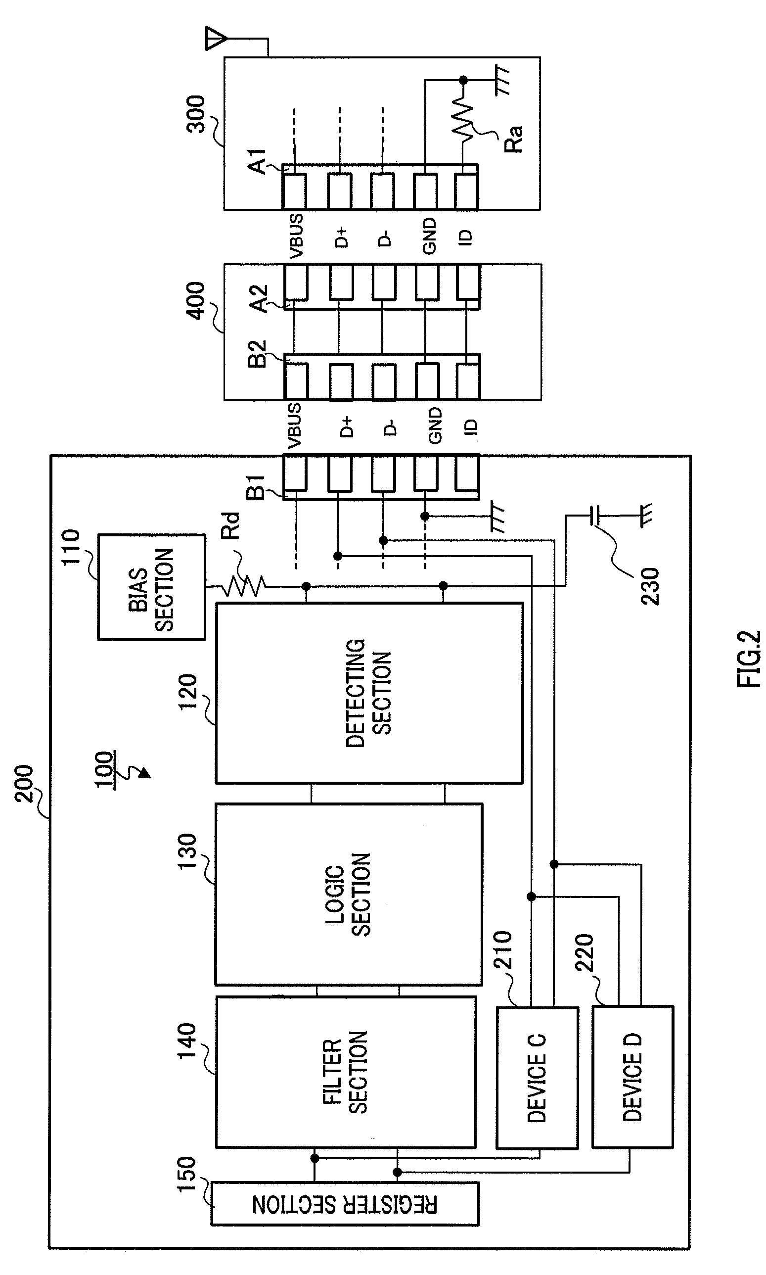
[0050]FIG. 2 is a diagram showing the configuration of the interface detecting circuit according to Embodiment 1 of the present invention. FIG. 3 is a detailed circuit diagram of the interface detecting circuit of FIG. 2. This embodiment is an example in which the interface detecting circuit is applied to a USB interface system.

[0051]In FIGS. 2 and 3, the USB interface system includes interface detecting circuit 100 and device 200, which implements the function of a USB device (hereinafter simply “device”), peripheral device 300, which implements the function of a USB host and USB cable 400, which connects device 200 with host 300.

[0052]Device 200 includes Mini-B receptacle B1, pull-up resistor Rd, bias section 110, detecting section 120, logic section 130, filter section 140, register section 150, device C210, device D220 and capacitor 230. Resistor Rs of peripheral device 300 and resistor Rd of device 200 are connected by USB cable 400 and one end of resistor Rd is connected to bi...

embodiment 2

[0112]FIG. 9 is a diagram showing the configuration of an interface detecting circuit according to Embodiment 2 of the present invention. FIG. 10 is a detailed circuit diagram of the interface detecting circuit of FIG. 9. Like reference numerals are assigned to the same components as FIG. 2 and FIG. 3 and description of overlapping sections will not be repeated.

[0113]In FIGS. 9 and 10, the USB interface system includes interface detecting circuit 100 and device (hereinafter simply “device”) 500, which implements the function of a USB device, peripheral device 300, which implements the function of a USB host, and USB cable 400, which connects device 500 and host 300.

[0114]Device 500 includes Mini-B receptacle B1, pull-up resistor Rd, bias section 110, detecting section 120, logic section 130, filter section 140, register section 150, charging section 510, battery 520 and capacitor 230. Resistor Rs of peripheral device 300 and resistor Rd of device 500 are connected by USB cable 400 a...

embodiment 3

[0163]FIG. 13 is a diagram showing the configuration of the interface detecting circuit according to Embodiment 3 of the present invention. FIG. 14 is a detailed circuit diagram of the interface detecting circuit of FIG. 13. Like reference numerals are assigned to the same components as in FIG. 2, FIG. 3, FIG. 9 and FIG. 10 and overlapping descriptions of such parts will not be repeated.

[0164]In FIGS. 13 and 14, the USB interface system includes main parts of interface detecting circuit 100A and device (hereinafter simply “device”) 600, which implements the function of a USB device, peripheral device 300, which implements the function of a USB host, and USB cable 400, which connects device 500 with host 300.

[0165]Device 600 includes Mini-B receptacle B1, pull-up resistor Rd, bias section 610, detecting section 620, logic section 630, filter section 640, register section 650, device C210, device D220, charging section 510, battery 520 and capacitor 230. Resistor Rs of peripheral devi...


PUM


Abstract

An interface detecting circuit and interface detecting method are provided, whereby operations can be carried out depending on peripheral devices connected to USB terminals, and whereby the system can be simplified and software load can be reduced. A pull-down resistor is connected to an ID terminal of a Mini-A receptacle of a peripheral device, the voltage generated by the pull-down resistor, which is pulled down by the ID terminal of the Mini-A receptacle of the peripheral device, and a pull-up resistor, which is pulled up by the ID terminal of a Mini-B receptacle of a device, is detected in an analog fashion, using a detecting section comprised of comparators, and, via a logic section, a logic output is subjected to noise cancellation in a filter section and is memorized in a register section. The operations of other devices are determined according to the states memorized in the register section.

Description

BACKGROUND OF THE INVENTION[0001]1. Field of the Invention[0002]The present invention relates to an interface detecting circuit mounted in electronic devices such as mobile devices and an interface detecting method. More particularly, in an interface system, in which a device and the host are connected through a USB (Universal Serial BUS) cable, the present invention relates to an interface detecting circuit and interface detecting method for detecting the type of the host and the connecting state on the device side.[0003]2. Description of the Related Art[0004]The USB has been widely used as a general-purpose interface. The USB is a standard specification, which is standardized by USB-IF (USB Implementers Forum) and a serious bus for connecting host devices such personal computers with peripheral devices such as a mouse and a keyboard. The USB offers features of allowing peripheral devices such as a keyboard, mouse, modem and joy stick to connect with a personal computer through a s...

Claims


Application Information

Patent Timeline
Patent Type & Authority Patents(United States)
IPC IPC(8): G06F3/00
CPCG06F13/4295
Inventor YOSHIDA, MASATOKAWAKAMI, YOSHIHITOARAI, SHIGENORIKIHARA, HIDEYUKI
Owner COLLABO INNOVATIONS INC
Why Eureka
Try Eureka