Seismic structural device

a technology of seismic structure and frame, which is applied in the direction of buildings, buildings, buildings, etc., can solve the problems of inability to use moment-resisting frames in taller structures, inability to meet the requirements of structural materials, and high cost, so as to soften the structure, and improve the dynamic characteristics of structures

Active Publication Date: 2010-05-11
SKIDMORE OWINGS & MERRILL LLP
View PDF18 Cites 31 Cited by
  • Summary
  • Abstract
  • Description
  • Claims
  • Application Information

AI Technical Summary

Benefits of technology

[0014]A “pin-fuse frame” consistent with the present invention enables a building or other structure to withstand a seismic event without experiencing significant inelasticity or structural failure at the pin-fuse frame. The pin-fuse frame may be incorporated, for example, in a beam and column frame assembly of a building or other structure subject to seismic activity. The pin-fuse frame improves a structure's dynamic characteristics by allowing the joints to slip under extreme loads. This slippage changes the structure's dynamic characteristics by lengthening the structure's fundamental period and essentially softening the structure, allowing the structure to exhibit elastic properties during seismic events. By utilizing the pin-fuse frame, it is generally not necessary to use frame members as large as those typically used for a similar sized structure to withstand an extreme seismic event. Therefore, building costs can also be reduced through the use of the pin-fuse frame consistent with the present invention.
[0015]The pin-frame frame provides for one or more “fuses” to occur within the structure. In a first embodiment, diagonal members within the frame may slip at a prescribed force level caused by the seismic event. Ends of beam members may not slip in rotation and this level of force. In another embodiment, as forces levels increase, the beam end may then slip or rotate. In addition, these behaviors occur in the structure in areas of highest demand. Therefore, some diagonal and beam members may not slip in a seismic event. In each case, the system is designed to protect the columns from inelastic deformations or collapse.

Problems solved by technology

In addition, the use of moment-resisting frames in taller structures may not be feasible since the required stiffness may only be achievable with large structural members that add to the amount of material required for the structure and therefore cost.
These frames provide an efficient means of achieving the appropriate stiffness, however provide questionable ductility when subjected to cyclic loadings.
Since ductility is limited in these frames, building codes, such as the Uniform Building Code (UBC), have limitations to their use.
Further, conventional braced frames that resist both tension and compression provide questionable ductility when subjected to cyclic seismic loading.
The braces in these frames typically buckle and in some cases fracture when further subjected to tension and compression loads.
The permanent deformation of the links within these frames raises serious questions about the structure's capability of resisting further seismic events without repair or replacement.
Recent testing of braced frames, particularly steel concentric braced frames (CBF), indicates that many commonly used members and brace configurations do not meet seismic performance expectations.
In recent seismic events, including the Northridge Earthquake in Northridge, Calif., moment-resisting frames within structures that used welded flange connections successfully prevented buildings from collapsing but these frames sustained significant damage.
After being subject to seismic loads, most of these types of moment-resisting frames have exhibited local failures of connections due to poor joint ductility.
Such frames with such non-ductile joints have raised significant concerns about the structural integrity and the economic performance of currently employed moment-resisting frames after being subject to an earthquake.
While these modified joints have been successful in increasing the ductility of the structure, these modified joints must still behave inelastically to withstand extreme seismic loading.
It is this inelasticity, however, that causes joint failure and in many cases causes the joint to sustain significant damage.
Although the amount of dissipated energy is increased by increasing the ductility, because the joints still perform inelastically, these conventional joints still tend to become plastic or yield when subject to extreme seismic loading.
Although current frames may resist seismic events and prevent collapse, the damage caused by the members and joints inability to function elastically, raises questions about whether structures that use these conventional designs can remain in service after enduring seismic events.
A need therefore exists for frames that can withstand a seismic event without experiencing significant inelasticity or failure so that the integrity of the structure remains relatively undisturbed even after being subject to seismic activity.

Method used


Image

  • Seismic structural device
  • Seismic structural device
  • Seismic structural device

Examples


Embodiment Construction

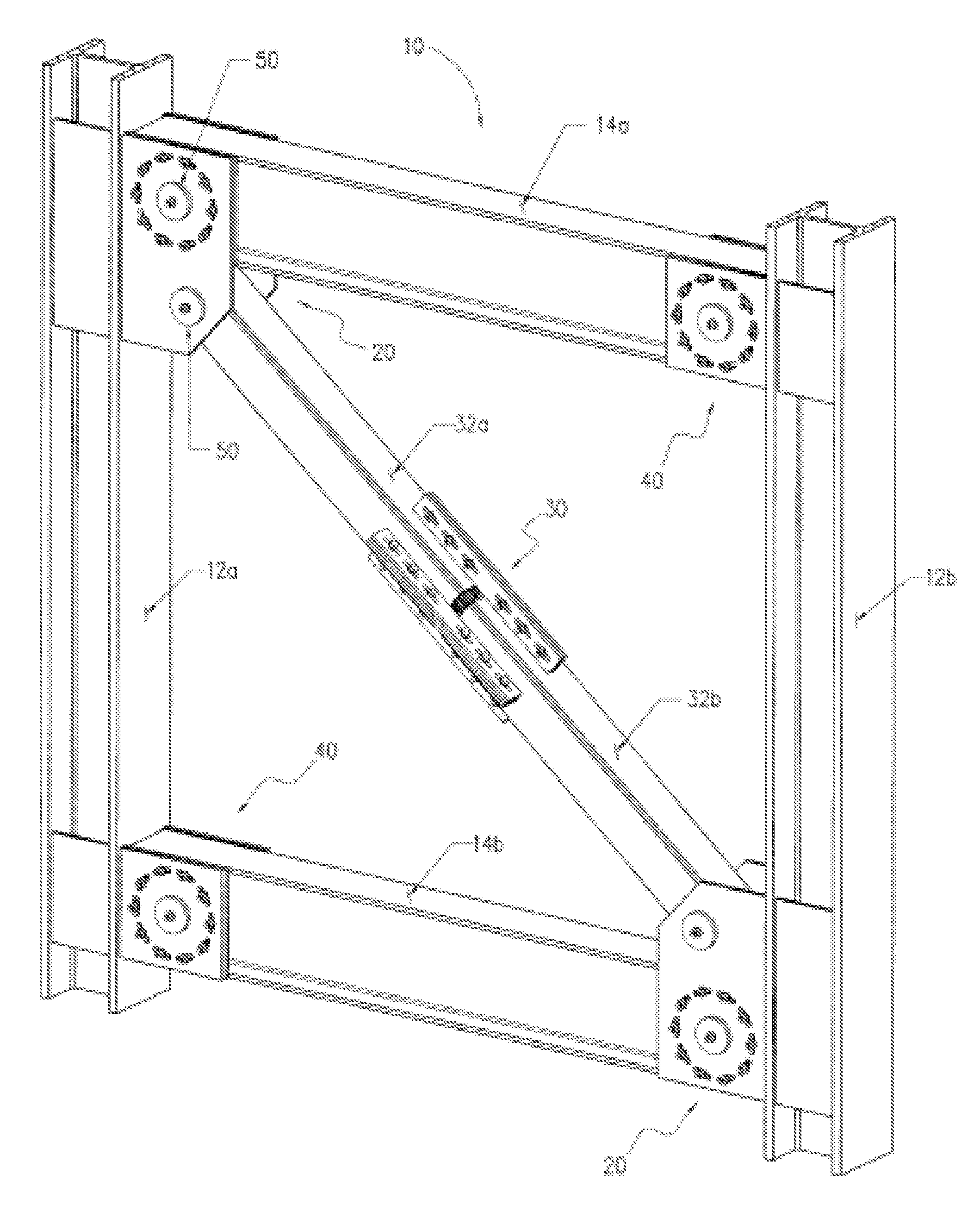
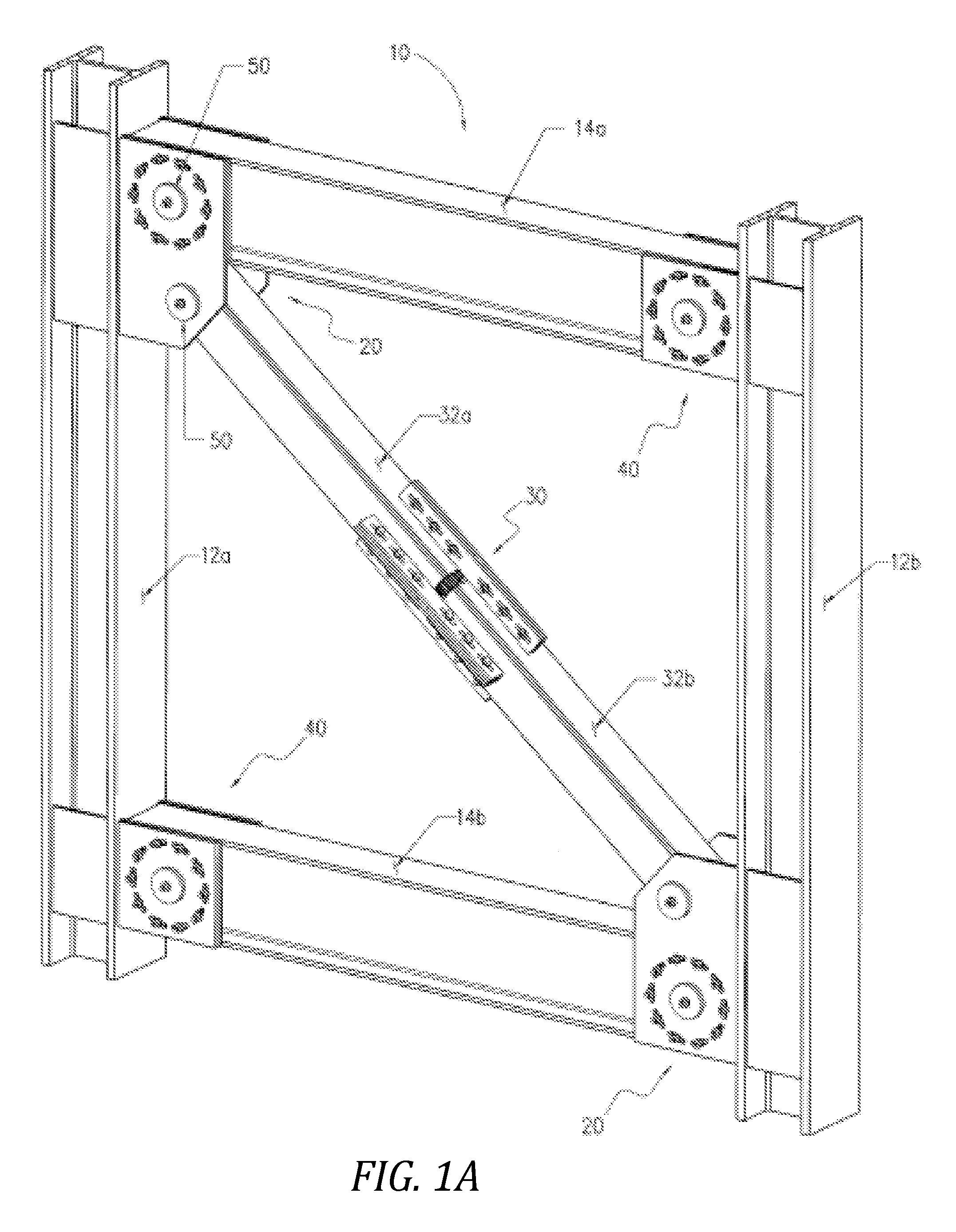
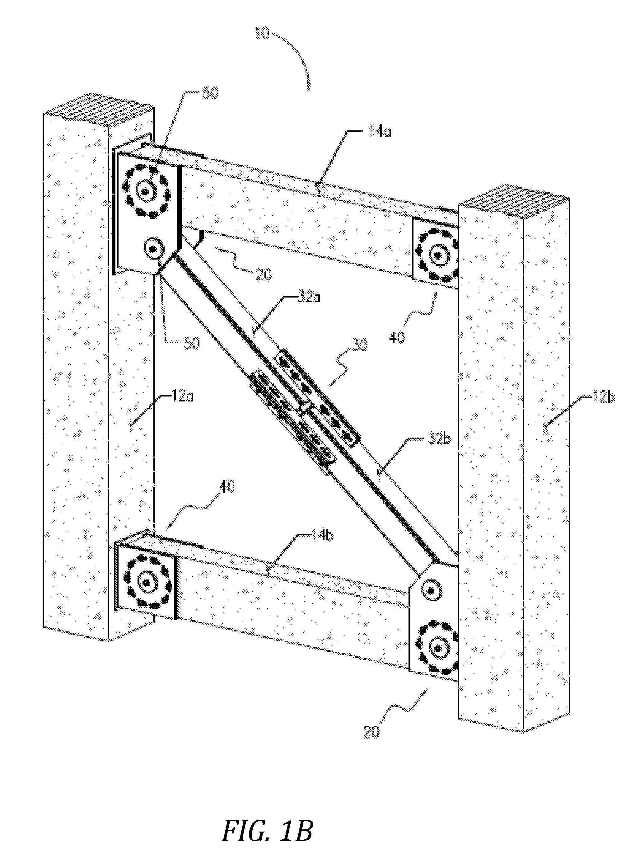
[0071]Reference will now be made in detail to an implementation in accordance with a pin-fuse frame consistent with the present invention as illustrated in the accompanying drawings. A pin-fuse frame consistent with the present invention enables a building or other structure to withstand a seismic event without experiencing significant inelasticity or structural failure at the pin-fuse frame. The pin-fuse frame may be incorporated, for example, in a beam and column frame assembly of a building or other structure subject to seismic activity and improves a structure's dynamic characteristics by allowing the joints to slip under extreme loads. This slippage changes the structure's dynamic characteristics by lengthening the structure's fundamental period and essentially softening the structure, allowing the structure to exhibit elastic properties during seismic events. By utilizing the pin-fuse frame, it is generally not necessary to use frame members as large as those typically used fo...


PUM


Abstract

A pin-fuse frame is used in a frame assembly that may be subject to extreme seismic loading. The pin-fuse frame includes of columns, beams, plate assemblies that extend between columns and beams, and may included a diagonal brace. The plate assemblies are fixed to the columns and attached to the beams and brace via pin joints. A joint includes a pin connection through outer connection plates connected to a column and inner connection plates connected to a beam. Connecting rods positioned about the pin maintain a coefficient of friction until exposed to extreme seismic activity, at which time the joint accommodates a slippage of at least one of the inner and outer connection plates relative to each other rotationally about the pin. The diagonal brace is separated into two segments connected together with connection plates. These connection plates accommodate a slippage of the segments relative to each other.

Description

BACKGROUND OF THE INVENTION[0001]1. Field of the Invention[0002]The present invention generally relates to a braced steel frame that is utilized in a structure that is subject to seismic loads. In particular, the braced steel frame is a pin-fused frame that lengthens dynamic periods and reduces the forces that must be resisted within the frame so that the frame can withstand seismic activity without sustaining significant damage.[0003]2. Description of the Related Art[0004]Structures have been constructed, and are being constructed daily, in areas subject to extreme seismic activity. Special considerations must be given to the design of such structures. In addition to normal loading conditions, the walls and frames of these structures must be designed not only to accommodate normal loading conditions, but also those loading conditions that are unique to seismic activity. For example, frames are typically subject to lateral cyclic motions during seismic events. To withstand such load...

Claims


Application Information

Patent Timeline
Patent Type & Authority Patents(United States)
IPC IPC(8): E04B1/98
CPCE04H9/02E04B1/2403E04H9/028E04H9/0237
Inventor SARKISIAN, MARK P.
Owner SKIDMORE OWINGS & MERRILL LLP
Why Eureka
Try Eureka