Downwardly accessible lift-and-shift ceiling system

a lift-shift ceiling and downward-accessible technology, applied in the direction of girders, snap fasteners, buckles, etc., can solve the problems of difficult manufacturing with the required dimensional tolerances, easy damage, etc., and achieve less dimensional control, less complexity in shapes, and easy cutting

Inactive Publication Date: 2010-05-11
USG INTERIORS INC
View PDF39 Cites 14 Cited by
  • Summary
  • Abstract
  • Description
  • Claims
  • Application Information

AI Technical Summary

Benefits of technology

[0005]The invention provides a downwardly accessible lift-and-shift suspended ceiling system that simplifies tile construction and thereby reduces manufacturing costs and difficulties as well as potential damage from mishandling. The invention achieves these benefits by assigning part of the tile centering function, in a unique manner, to specialized centering elements on the grid tees.
[0008]With the locating surfaces serving to horizontally position the tiles in the grid, the rabbets need less complexity in their shapes and are, therefore, easier to cut and involve less dimensional control. Besides being less susceptible to damage when being handled, ceiling tiles constructed in accordance with the invention with a proper kerf or edge design that do sustain physical damage that might detract from their ability to be properly centered when installed on a grid are readily seen and, therefore, can be corrected, or can be rejected by the installer before being installed.

Problems solved by technology

These stepped edges can be difficult to manufacture with the required dimensional tolerances and can be susceptible to damage during shipment, handling, and installation.

Method used


Image

  • Downwardly accessible lift-and-shift ceiling system
  • Downwardly accessible lift-and-shift ceiling system
  • Downwardly accessible lift-and-shift ceiling system

Examples


Embodiment Construction

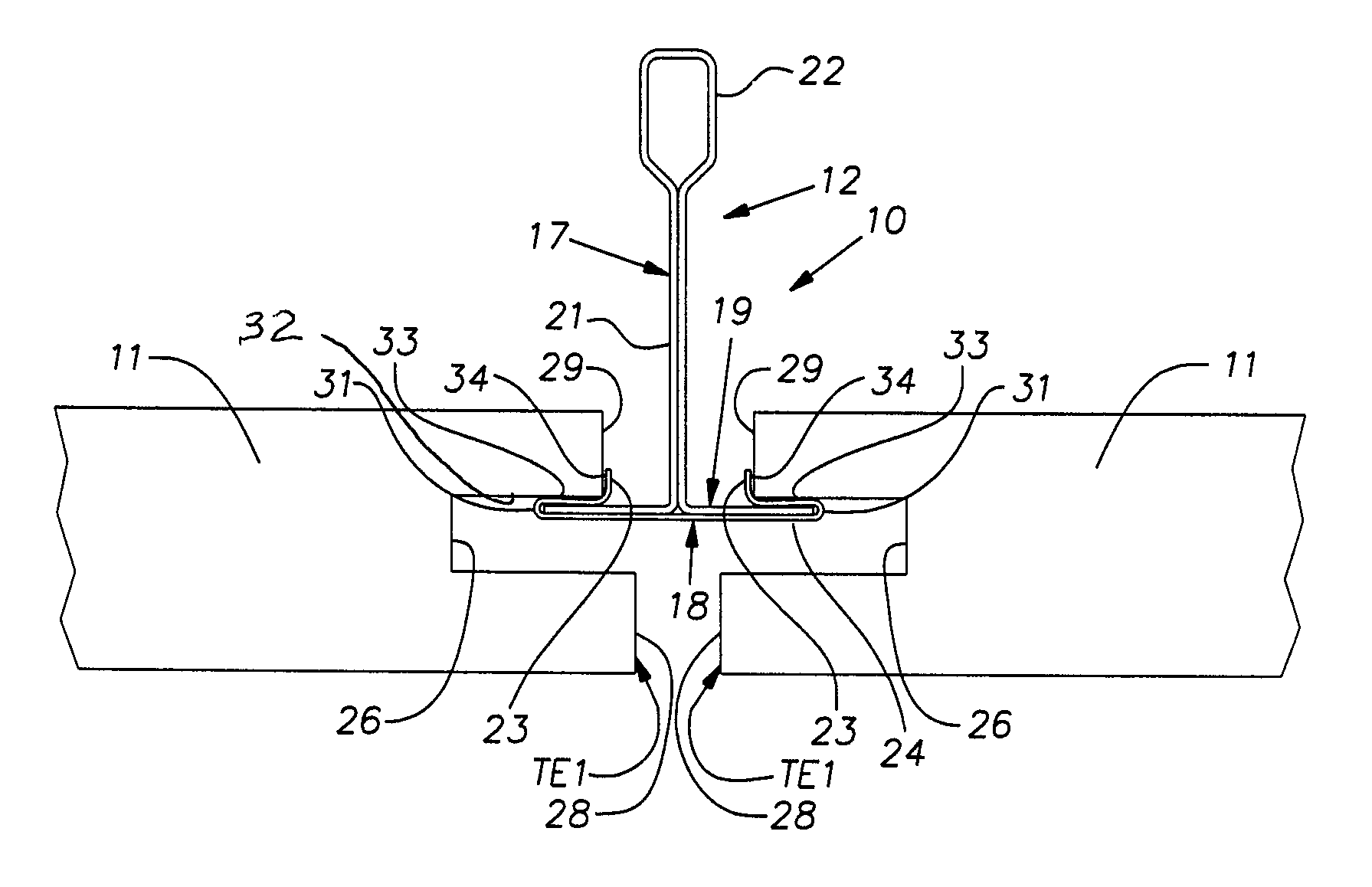
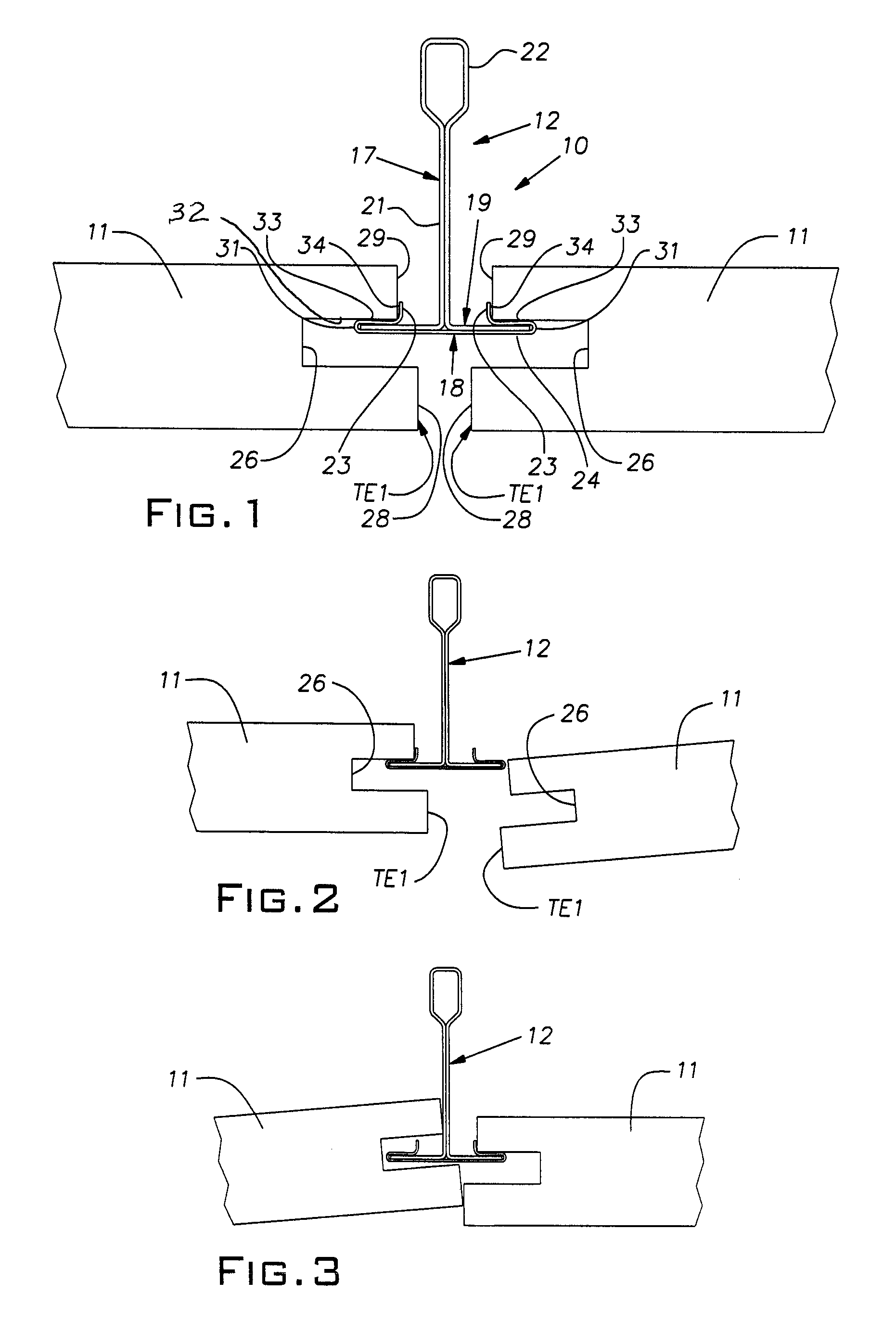
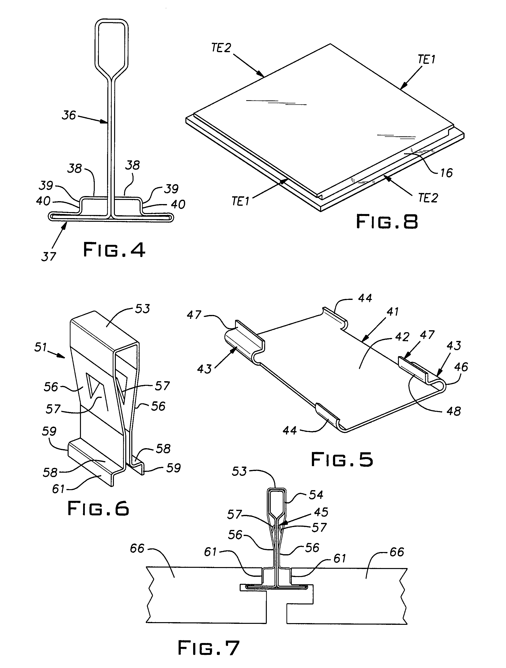
[0017]Referring now to the figures, a suspended ceiling system 10 comprises ceiling tiles 11 carried on grid tees 12. A pair of ceiling tiles 11, partially shown in FIGS. 1-3, and fully in FIG. 8, are mounted on grid tees, one of which is shown in FIGS. 1-3. The tiles 11 are of any rigid relatively low density composition, known in the art, and typically have acoustic and fire-resistant properties. The tiles 11, as shown in FIG. 8, are generally planar and rectangular in plan view, being typically nominally 2 foot by 2 foot (or metric equivalent) square or rectangular with 2 foot by 4 foot (or metric equivalent) nominal dimensions. The tiles 11 have edge details that are the same at opposite parallel edges but, with respect to a specific edge, is different at adjacent perpendicular edges. Tile edges TE1 correspond to rabbeted grooved edges shown in FIGS. 1-3, and tile edges TE2 are simply rabbeted, preferably with a square cut, and can be devoid of any groove or undercut. Vertical e...


PUM


Abstract

A suspended ceiling system comprising grid runners and downwardly accessible generally planar tiles mounted on the grid runners, peripheral tile edges having portions extending horizontally underneath an adjacent grid runner, opposed tile edges having a downwardly facing support surface, said opposed edges having a generally vertical abutment surface above its support surface and resting on an adjacent horizontal flange portion of a grid runner, the runners having locating surfaces of limited height above said flange portions and engageable with the abutment surfaces, the runners and tiles being arranged to permit one of the opposed tile edges to be lifted so that its abutment surface can be raised and thereafter be shifted towards the runner adjacent the lifted edge a distance sufficient to allow the opposite edge to drop below the flange portion of its associated runner.

Description

BACKGROUND OF THE INVENTION[0001]The invention relates to suspended ceiling grid tee and tile structure of a type, useful in applications where overhead clearance is limited, that can be removed downwardly.PRIOR ART[0002]Suspended ceilings typically comprise a metal grid of intersecting runners, usually in the form of inverted tees, and rectangular tiles supported on the grid runners or tees.[0003]Downwardly accessible lift-and-shift tiles have been developed. Examples of such prior art are shown in U.S. Pat. Nos. 6,108,994 and 6,389,771, for example. Downward accessibility offers the recognized benefits of a suspended ceiling with removable and / or replaceable tiles and, additionally, the ability to be used where overhead clearance is limited. Among other benefits, this low clearance feature can be used in the original design of a building to save height at each floor level. In a high rise building, this height reduction can amount to a considerable savings of material and, therefor...

Claims


Application Information

Patent Timeline
Patent Type & Authority Patents(United States)
IPC IPC(8): E04B9/00E04B9/28A44B99/00
CPCE04B9/003E04B9/068E04B9/247E04B9/28E04C3/07Y10T24/44923E04C2003/0421E04C2003/043E04C2003/0452E04B9/0435
Inventor WENDT, ALAN C.KOSKI, GERALD L.
Owner USG INTERIORS INC
Why Eureka
Try Eureka