
Communication jack

a communication jack and connector technology, applied in the direction of coupling device connection, contact member penetration/cutting insulation/cable strand, coupling parts engagement/disengagement, etc., to achieve the effect of saving operating space, simplifying assembly process, and reducing labor hours

Inactive Publication Date: 2010-05-11
SURTEC INDS
View PDF19 Cites 30 Cited by
  • Summary
  • Abstract
  • Description
  • Claims
  • Application Information

AI Technical Summary

Benefits of technology

"The present invention is a communication jack that has parts for fixing and grounding a cable integrated within it. This makes the assembly easier and safer, as it reduces the risk of damage. The jack includes a first member, a second member, and a clamping component. The cable passes through the clamping area and extends to a place between the first member and the second member. The clamping component is displacedly disposed in the operating slot of the first member, and normally extends into the clamping area to press against the cable, thus gripping it and keeping it in contact with the ground wire mesh. This simplifies the assembly process, reduces labor hours, and saves operating space. Additionally, the clamping component provides protection against external forces, reducing the need for additional parts and avoiding the risk of parts falling apart or getting lost."

Problems solved by technology

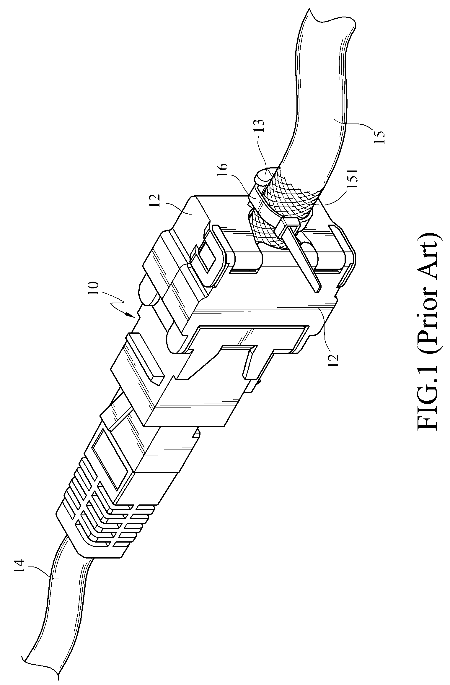
In the communication jack of the prior art, the parts for fixing and grounding a cable are separated from the jack, so that the assembly is inconvenient and easily cause damages.

Method used


Image

  • Communication jack
  • Communication jack
  • Communication jack

Examples


Embodiment Construction

[0024]The objectives, structures, features, and functions of the present invention will be illustrated in detail below in the accompanying embodiments.

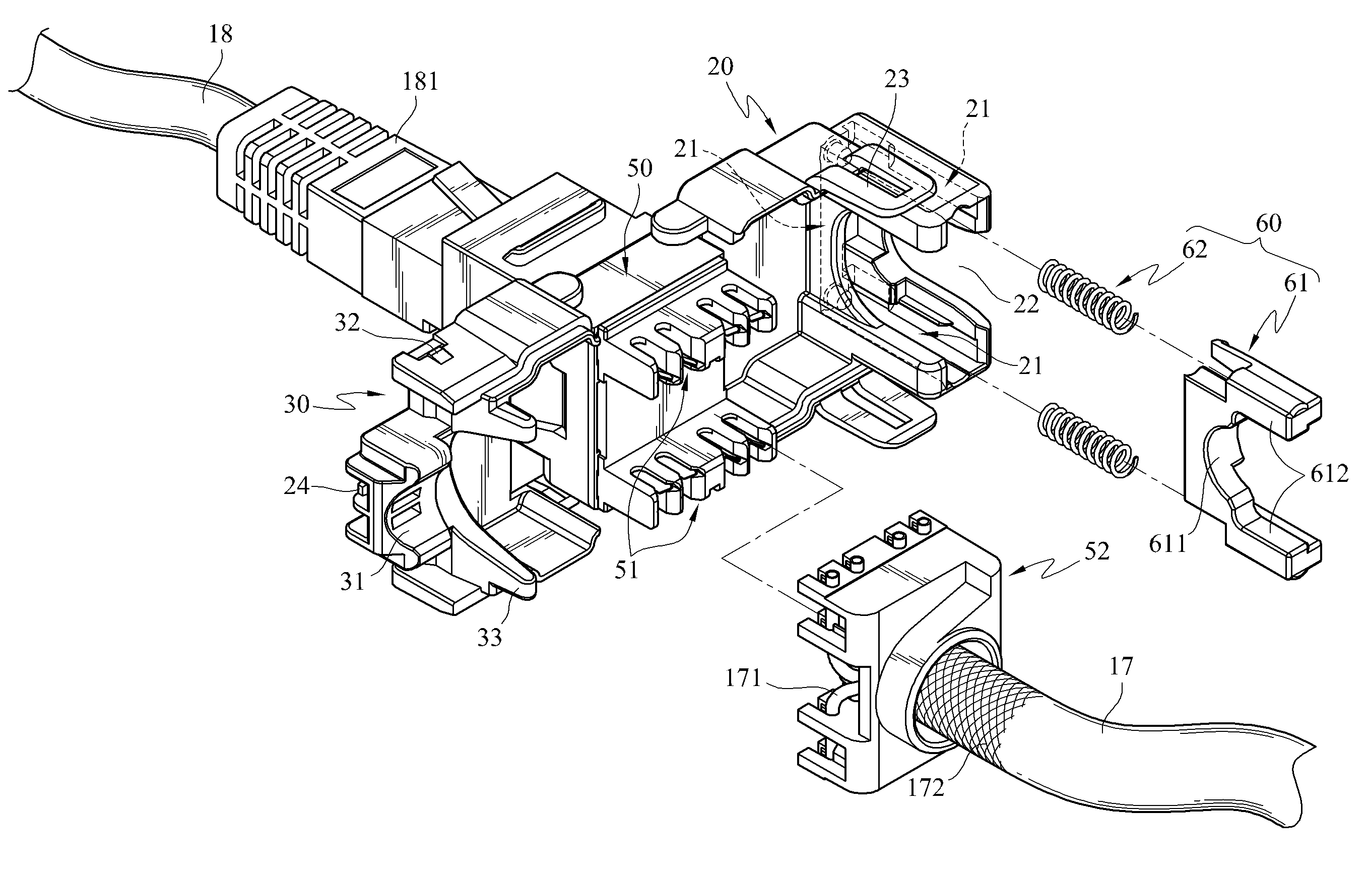
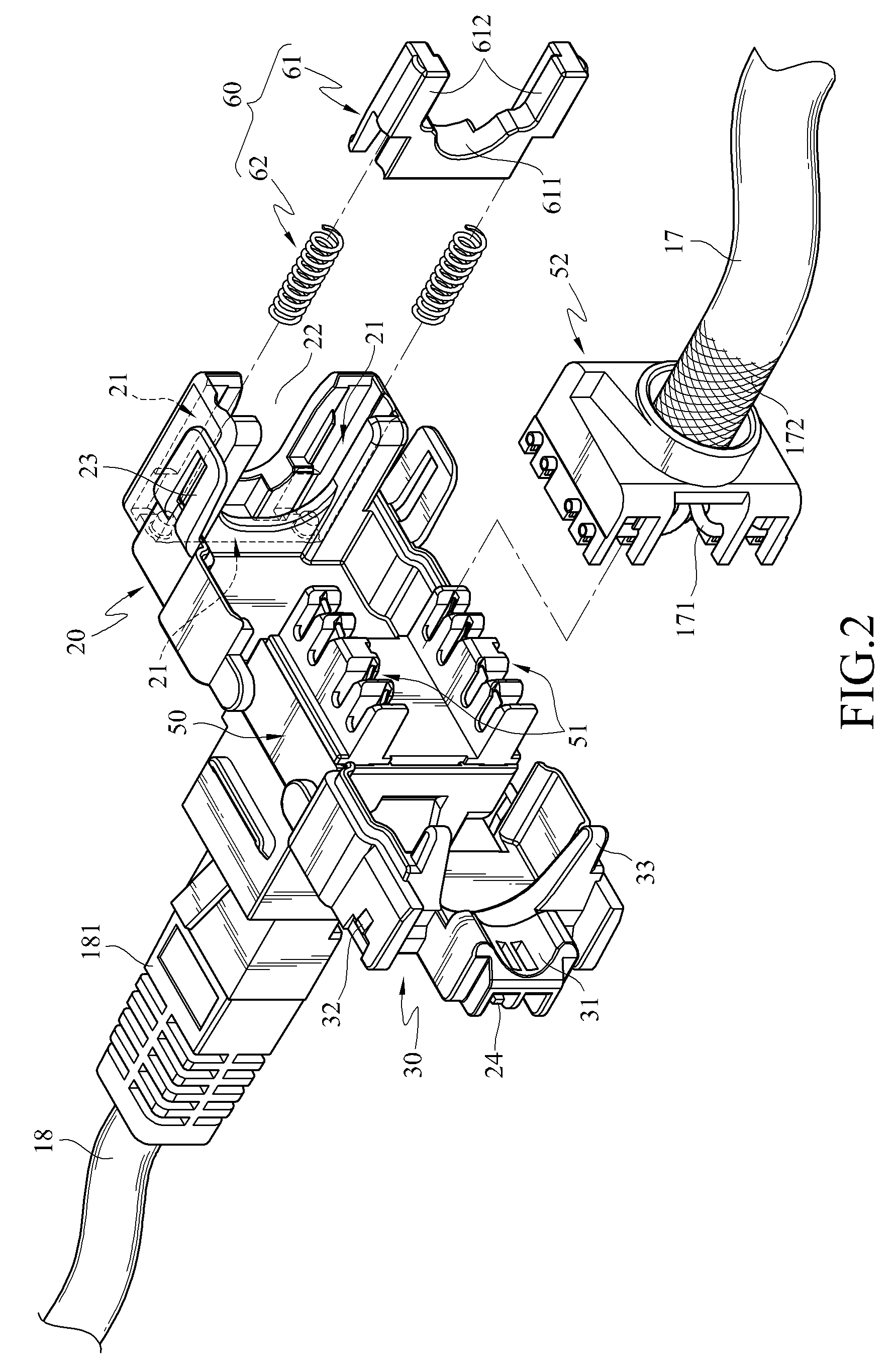
[0025]Referring to FIGS. 2 to 6, a first embodiment of the present invention is shown. According to the first embodiment of the present invention, a communication jack electrically connects a cable 17 and a cable 18. The communication jack of this embodiment includes a first member 20, a second member 30, a base 50, and a clamping component 60, which are all made of a conductive material, such as copper, iron, aluminum, or other metal materials.

[0026]The cable 18 is a network or telecommunication connection line with an adapter 181 on the front end. The cable 17 has a plurality of wires 171 and a layer of ground wire mesh 172 wrapped around the wires 171. The ground wire mesh 172 is woven, for grounding and isolating the cable 17 from external signal interferences. During the layout, the front end of the cable 17 is cut open to expose...


PUM


Abstract

A communication is jack adapted to connect a cable that has an exposed ground wire mesh. The communication jack includes a first member, a second member, and a clamping component. The second member and the first member are capable of pivotally rotating relatively to be combined to form a clamping area. The cable is gripped by the clamping component and the second member in the clamping area, and the clamping component and the second member keep in contact with the ground wire mesh of the cable. Thus, the cable is fixed and grounded by simply combining the first and second members.

Description

CROSS-REFERENCE TO RELATED APPLICATIONS[0001]This non-provisional application claims priority under 35 U.S.C.§119(a) on Patent Application No(s). 097210345 filed in Taiwan, R.O.C. on Jun. 11, 2008 the entire contents of which are hereby incorporated by reference.BACKGROUND OF THE INVENTION[0002]1. Field of Invention[0003]The present invention relates to an electric signal connector, and in particularly, to a communication jack capable of fixing and grounding a cable at the same time.[0004]2. Related Art[0005]Connectors are basic parts commonly seen in the electro-communication field, and almost various electronic devices are installed with connectors serving as the medium for connecting the electronic devices to an external electric signal. Among various types of connectors, some can be directly inserted with a cable (for example, a network line or telephone line) so as to be electrically connected thereto, and this kind of connector is referred to as a communication jack for connec...

Claims


Application Information

Patent Timeline
Patent Type & Authority Patents(United States)
IPC IPC(8): H01R13/58
CPCH01R9/037H01R9/0527H01R4/2433H01R24/64H01R13/5829H01R13/65917
Inventor CHEN, CHOU-HSING
Owner SURTEC INDS
Learn More