Acylindrical optical device

a technology of optical devices and axis, applied in the field of optical devices, can solve the problems of reducing the diameter of the lens, difficult and expensive manufacturing of products that achieve the goals of achieving these goals, and the ability to make smaller optical devices including those with lens systems, and achieves high centering accuracy, high quality of lenses, and efficient manufacturing

Inactive Publication Date: 2010-05-11
INTUITIVE SURGICAL OPERATIONS INC
View PDF40 Cites 13 Cited by
  • Summary
  • Abstract
  • Description
  • Claims
  • Application Information

AI Technical Summary

Benefits of technology

[0015]Another object of this invention is to provide a lens element with high centering accuracy and with cross sectional dimensions of less than approximately 1 mm.
[0016]Still another object of this invention is to provide a method for efficiently manufacturing a high quality lens or lens system from a conventional lens or lens system useful in optical devices with a reduced outer diameter to less than 1mm.

Problems solved by technology

However products that achieve these goals are difficult and expensive to manufacture with traditional lens making methods.
The ability to make smaller optical devices including those with lens systems that continue to exhibit centered rotationally symmetrical characteristics, becomes more difficult as the lens diameter reduces.
However, to achieve an absolute tolerance as a constant percentage of very small diameters requires extreme accuracy and tools that operate with extremely close tolerances.
Machines for providing such accuracies become increasingly expensive as tolerance requirements become more stringent.
At small diameters it becomes difficult to support the lens element so that its optical axis remains in a single position relative to a tool reference.
Moreover, as the diameter decreases the lens element becomes, in effect, more brittle and thus extremely fragile.
These factors lead to an increased potential for breakage during manufacture.

Method used


Image

  • Acylindrical optical device
  • Acylindrical optical device
  • Acylindrical optical device

Examples


Embodiment Construction

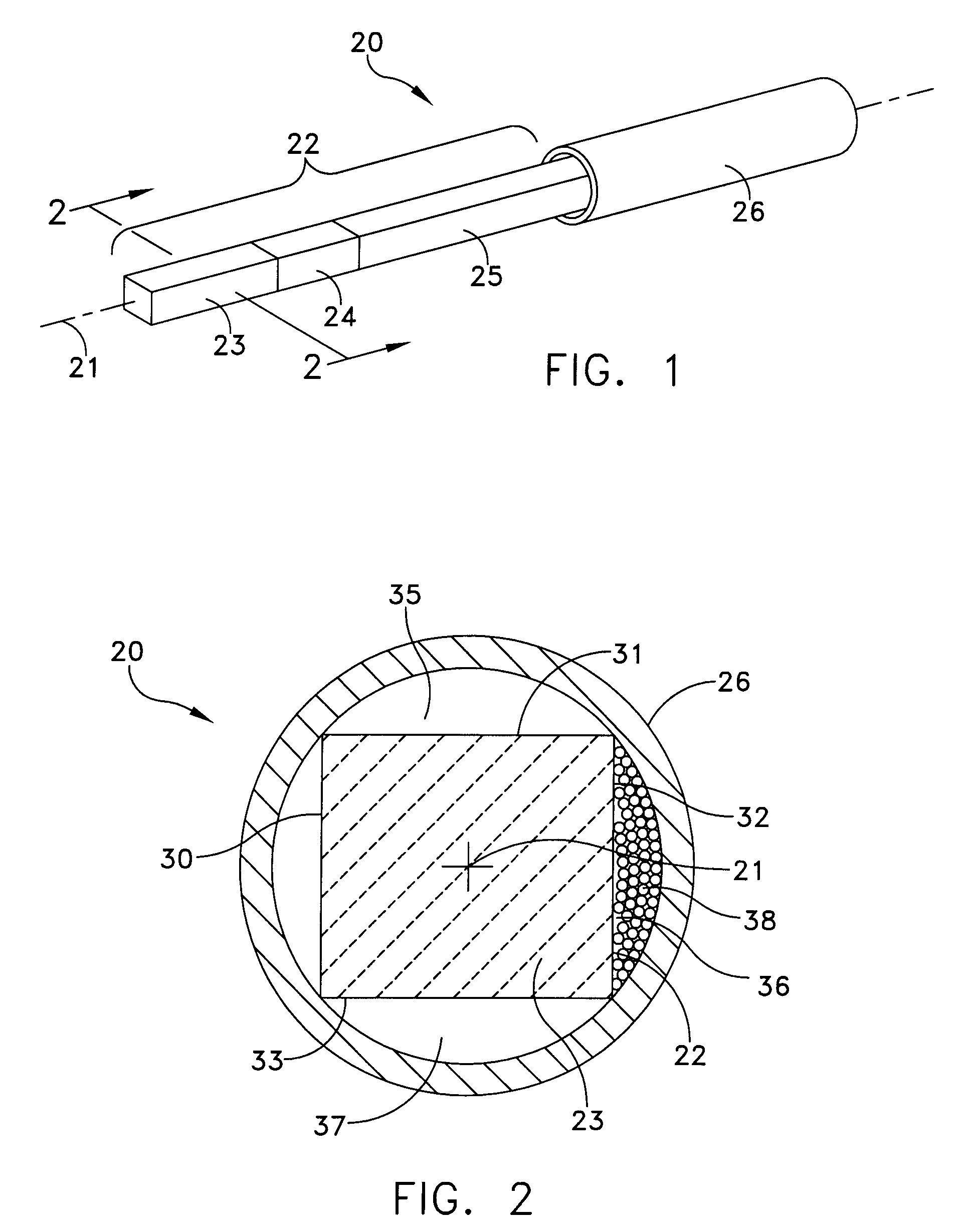
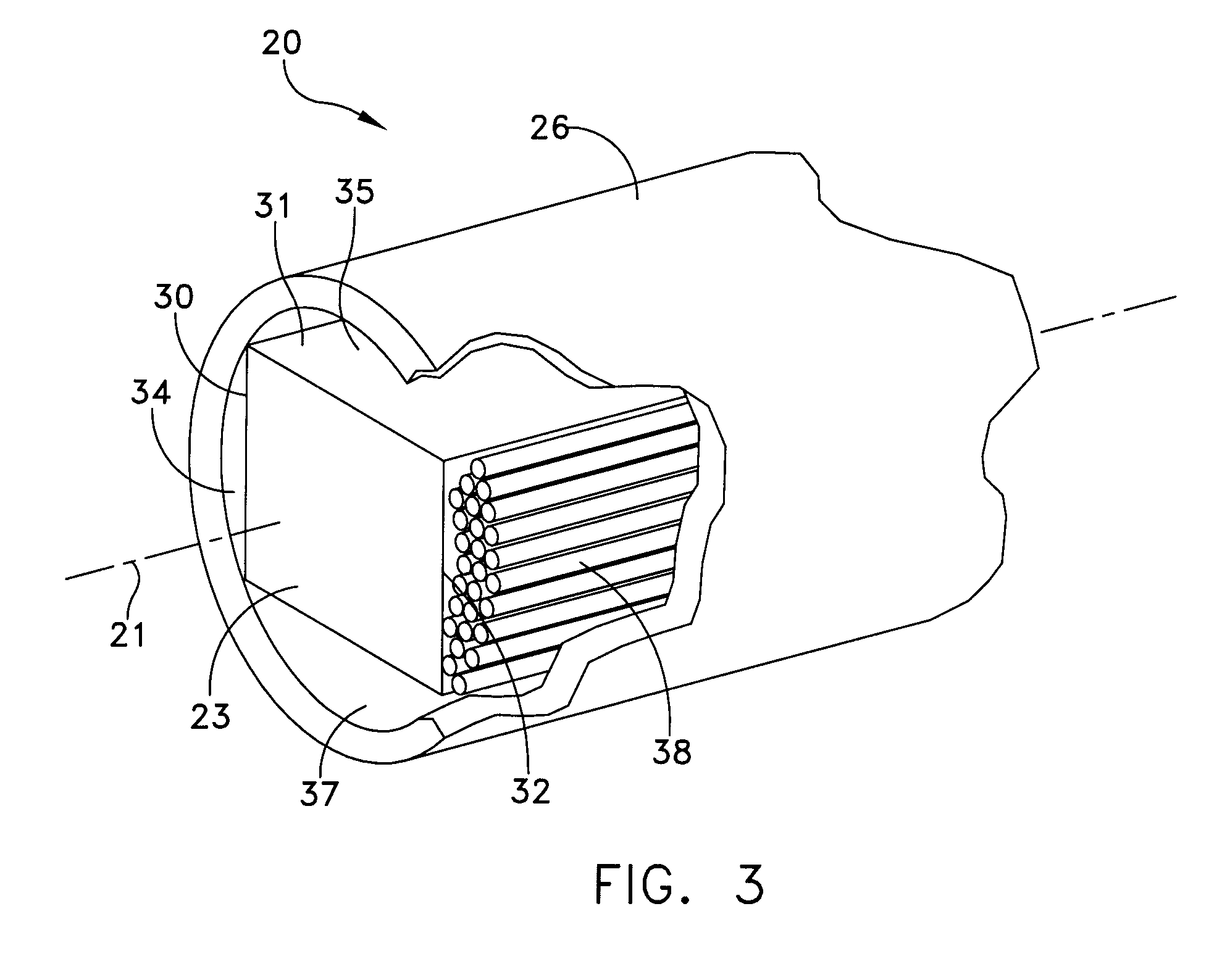
[0035]FIGS. 1 through 3 depict a portion of an optical device 20, such as an endoscope, constructed in accordance with this invention that lies along an axis 21. In this embodiment, the optical device 20 includes a lens system 22 with adjoined lens elements 23, 24 and 25. In this particular embodiment, each of the lens elements 23, 24 and 25 and the lens system 22 have centered rotational symmetry with respect to the axis 21 so the optical and geometric axes of the optical device are coincident. Although not shown, but as will be known to persons of ordinary skill in the art, the end surfaces of each lens element constitute image forming surfaces that are polished, generally spherical surfaces that produce an image of any object proximate the axis 21. As manufacture and use of lens elements with such surfaces are known, FIGS. 1 through 3 do not depict a specific spherical surface. A flat traverse surface is shown as a representation of an entire class of image forming surfaces.

[0036...


PUM


Abstract

A lens structure and method for manufacture of such a lens. A lens element has multiple sawn planar faces between image forming surfaces so the lens element has a polygonal cross section. The manufacture includes the step of utilizing oversized conventional cylindrical lens elements and other optical elements formed into lens systems. The faces are sawn to reduce the overall size. The sawing can be applied to integral lens elements or assemblies or lens arrays.

Description

CROSS REFERENCE TO RELATED APPLICATION[0001]This application is a continuation-in-part of U.S. patent application Ser. No. 10 / 659,727 filed Sep. 10, 2003 now U.S. Pat. No. 7,116,486 granted Oct. 3,2006 for Acylindrical Optical Devices and Method of Manufacture, which patent is assigned to the same assignee as this application.BACKGROUND OF THE INVENTION[0002]1. Field of the Invention[0003]This invention generally relates to optical devices and methods for the manufacture of such optical devices and more particularly to optical devices with lens systems of a small diameter or cross section.[0004]2. Description of Related Art[0005]Endoscopes are examples of optical devices that utilize optical systems characterized by an assembly of a plurality of optical elements, such as lenses, that are serially disposed along an optical axis. In an endoscope, for example, a lens system comprising multiple lens elements at a distal end constitutes an objective; a lens system at the proximal end con...

Claims


Application Information

Patent Timeline
Patent Type & Authority Patents(United States)
IPC IPC(8): G02B3/00G02B11/00G02B9/00G02B7/00G02B13/00G02B15/00G02B17/00G02B25/00G02B7/02G02B23/24
CPCG02B7/02G02B23/2476G02B23/2446
Inventor FORKEY, RICHARD E.CYR, RICHARD G.ROSS, ROBERT N.FORKEY, JOSEPH N.
Owner INTUITIVE SURGICAL OPERATIONS INC
Why Eureka
Try Eureka